background image


Medium Capacity LP Tank


The Type 1 connection system has the following features: The system will not allow gas to flow 
until a positive connection has been made. NOTE: The cylinder control valve must be turned off 
before any connection is made or removed. The system has a thermal element that will shut off 
the flow of gas in the event of a fire. The system has a flow limiting device which, when activated, 
will limit the flow of gas to 10 cubic feet per hour. NEVER use grill without leak testing. 


GAS SETUP – MEDIUM CAPACITY LP TANKS 


PAGE 12 

Follow Instructions:


The tank valve & all Knobs should be in the “OFF” position. If not, turn the knob clockwise until it 
stops. 


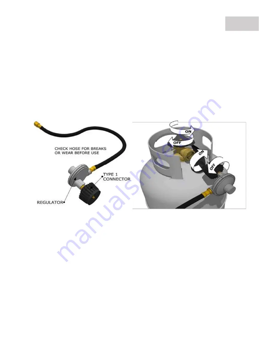
Insert the regulator inlet into the tank valve and turn the coupling nut clockwise until the coupler 
tightens up (see picture above). Do not overtighten the coupler. Turn the main tank valve on and 
turn the grill control valves on the unit to the “HIGH” position for about 20 seconds to allow the 
air in the system to purge before attempting to light the burners. 


Summary of Contents for SUNCHSZ30

Page 1: ...ate your grill Save these instructions To installer or person assembling grill Leave this manual with grill for future reference To consumer Keep this manual for future reference www sunstonemetalprod...

Page 2: ...Tank Please make sure you have the following information MODEL NUMBER DATE OF PURCHASE INVOICE NUMBER For warranty service contact SUNSTONE Customer Service Department at 888 934 9449 or email service...

Page 3: ...SION Indicates an imminently hazardous situation which if not avoided will result in possible explosion and cause death or severe injury BODILY INJURY Indicates a potentially hazardous situation which...

Page 4: ...e maintained All packaging has been removed from Interior of Grill All parts and components are properly installed An installer supplied manual gas shut off valve is fully accessible LP hose is clean...

Page 5: ...GRILL PARTS PARTS INDEX PAGE 1...

Page 6: ...GRILL PARTS PARTS DIAGRAM PAGE 2...

Page 7: ...the Light Button on Left side of grill control panel The Transformer s electrical connection to grill is located behind control panel next to light button The connection clips together to form a secu...

Page 8: ...n the back of unit which allow proper airflow out of the back of grill Be sure to allow a minimum of 6 behind grill for proper air ventilation and to allow hood to open properly Push grill all the way...

Page 9: ...ILL INSTALLATION PRODUCT DETAILS PAGE 5 Technical Measurements See measurement box next page If the cut out is smaller than what ours is shown or you are installing grill into cabinet structure you ma...

Page 10: ...llation A Grill Cut out Depth 22 Depth B Grill Cut out Height Allow Air Flow Gap Below Drip Pan 12 3 4 Height C Grill Cut out Width 27 1 2 Width D Make 1 3 4 W x1 D Notch Cut Out on both sides of cut...

Page 11: ...ior outside wall or roof and there is a Minimum of Two adjacent sides which are open with outside exposure PAGE 7 ATTENTION All Gas Grill Installations MUST HAVE MINIMUM TWO AIR FLOW VENTS either in E...

Page 12: ...lor or damage unprotected areas do not install under unprotected combustible construction without using a fire safe ventilation system A 24 minimum clearance must be maintained under the countertop to...

Page 13: ...our Warranty may be VOID if island does not meet basic setup requirements GRILL INSTALLATION ENCLOSED INSTALLATION PAGE 9 Enclosed Installation Definition Structure built above Appliance that is attac...

Page 14: ...ake sure BBQ Grill control knobs are in OFF position Verify the type of gas supply to be used either Natural Gas or Liquid Propane and make sure the marking on the appliance rating label agrees with t...

Page 15: ...with an independent LP regulator for this type of installation Contact the company you purchased from or your local plumber to locate one that is made for commercial style grills Large Capacity LP Tan...

Page 16: ...limit the flow of gas to 10 cubic feet per hour NEVER use grill without leak testing GAS SETUP MEDIUM CAPACITY LP TANKS PAGE 12 Follow Instructions The tank valve all Knobs should be in the OFF posit...

Page 17: ...NATURAL GAS INSTALLATION PAGE 13 Follow Instructions The tank valve all Knobs should be in the OFF position If not turn the knob clockwise until it stops Insert the regulator inlet into the tank valv...

Page 18: ...the cooking grids If the burner does not light on the first try repeat immediately 4 If the burner does not light in 5 seconds then wait five minutes until the gas clears before attempting to light it...

Page 19: ...nside is a grate to hold the briquettes and to keep them above the crumpled newspaper which goes in under the charcoal and is what starts the briquettes Ventilation holes line the bottom of the tube T...

Page 20: ...e amazing smoked flavors Indirect Cooking Indirect cooking is the process of cooking your food without the heat source directly under your food You can sear meats over a high flame on one side of the...

Page 21: ...et 5 Before placing food item on forks when the rotisserie is being operated exclusively it is strongly recommended that a pan be placed on the grilling grids beneath the food to catch the meat drippi...

Page 22: ...of meat being cooked You can have rotisserie cooking with indirect heat or with infrared rotisserie burner Preferred by professional chefs over other methods the intense heat is ideal for searing in t...

Page 23: ...across and stay on There is a Brass Wire called the Thermocouple it must be heated all the way down to the valve for the gas to stay on TIP If IR Burner does not stay lit try running the bottom burne...

Page 24: ...e Appliance Control Panel were Knobs are located For Propane Gas Liquid Propane Gas LP is Heavier and will lower to base of structure upon leak Outdoor Kitchen Islands housing Propane Gas Appliance mu...

Page 25: ...are Adapter to NG gas type 1 Reveal Grill Firebox Remove from the Grill ALL Burn Trays Cooking Grates and clean out any residue Turn the Burn Tray Crank so that the Burn Tray Rack is placed in the low...

Page 26: ...be very difficult to pull it back up as it is a very small area with limited access under burner compartment 4 Push the Flare Adapter Out Push the Flare Adapter out through the port hole while keepin...

Page 27: ...ifice Hole approx 1 8th Inch then pulling out lastly blow some air into tip clearing any small particles 8 Screw on the NG Regulator Fasten on the NG Regulator with the Female Flare Adapter connecting...

Page 28: ...ss Flare Adapter mounted on the inside compartment 11 Remove Brass O Ring to Release Flare Once the flare is removed pull the orifice end out so it is accessible 12 LP to NG Gas Conversion For convert...

Page 29: ...make sure each is securely pushed in If all the Lights do not work then it is either unplugged or the Transformer has malfunctioned Each Halogen light can be replaced by unscrewing a single screw per...

Page 30: ...ntingent damages resulting from its breach of this written warranty or any implied warranty 6 Some states do not allow limitations on how long an implied warranty lasts or the exclusions of or limitat...

Reviews: