background image

4

Unmanned ship, Unmanned car, Airship, Target drone, Powered parachute, Robot and

other fields for video signal transmission, police video forensics, emergency monitor

and rescue sites.

Ⅲ、Cautions

The device data interface is designed by air plug. If it needs to be extended during

use, please use the direct network cable. The direct network cable sequence is defined

as follows:

Special attention: before the equipment is powered on, please carefully confirm

whether the antenna is correctly connected, so as to avoid unnecessary trouble and

economic loss caused by damage to the equipment.

Ⅳ、Equipment Debug

4.1 Prepare of Debug

Before debugging, ensure that PC and device IP in the same network segment.

Factory default parameters: IPv4 address: 192.168.1.1; Subnet mask: 255.255.255.0;

The IP of the computer should be set to 192.168.1.x (X= any number between 2 and

253, which does not conflict with the device address).

The subnet mask:255.255.255.0。

Summary of Contents for ST15NMT-MiNi

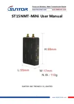
Page 1: ...1 ST15NMT MiNi User Manual SUNTOR ELECTRONICS CO LIMITED...

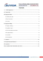
Page 2: ...asic Parameters 5 3 3 Cautions 5 Equipment Debug 6 4 1 Prepare of Debug 6 4 2 Equipment Login 7 4 3 Set Central Node Access Node 7 4 4 Modify IP Address 8 4 5 Set WLAN 9 4 6 Set Bandwidth 9 Use Notes...

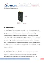
Page 3: ...in 1 4G frequency it can realize a high throughput Ad hoc network transmission in a long LOS distance When it s in 800M frequency it can realize fast mobile Ad hoc network transmission in a NLOS comp...

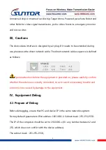
Page 4: ...lows Special attention before the equipment is powered on please carefully confirm whether the antenna is correctly connected so as to avoid unnecessary trouble and economic loss caused by damage to t...

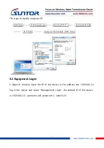
Page 5: ...er IP 4 2 Equipment Login 1 Open IE browser input the IP of the device in the address bar 192 168 1 12 log in the device and select Management Login the default IP of the device is 192 168 1 12 userna...

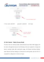
Page 6: ...to the device through the browser the following actions are required to change the device s working mode After entering the page click Master and Slave Setting select Master and Slave Setting to set t...

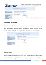
Page 7: ...IP setting to modify the de vice IP address Click OK to complete IP modification as shown in figure 4 5 Set WLAN When setting the working frequency of the device click the Wireless Setting button and...

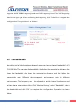
Page 8: ...z The narrower the bandwidth the farther the transmission distance the lower the bandwidth the closer the transmission distance and the higher the transmission rate Different electromagnetic environme...

Page 9: ...different channels to avoid electromagnetic interference Do not twine the network wire with the power wire or there will be magnetic interference Network wire and power wire shall not exceed 20m Set t...

Page 10: ...92 168 1 xx the default IP of the equipment is 192 168 1 1 xx stands for specific IP so as to determine whether the device is online or not The same method is used to troubleshooting other devices If...

Page 11: ...icate the parameters can be adjusted according to the above debugging instructions also you can restore factory setting according to the Quick Use Manual to set Accessories Item Quantity Specification...

Reviews: