IOM-WR-TapeMat 1526
14 of 32
STEP 3.7
Use a digital multi-meter to measure the
resistance between the conductors of the
power leads again. Record these resistances in
Table 4
under “After mat is secured in place”.
STEP 3.8
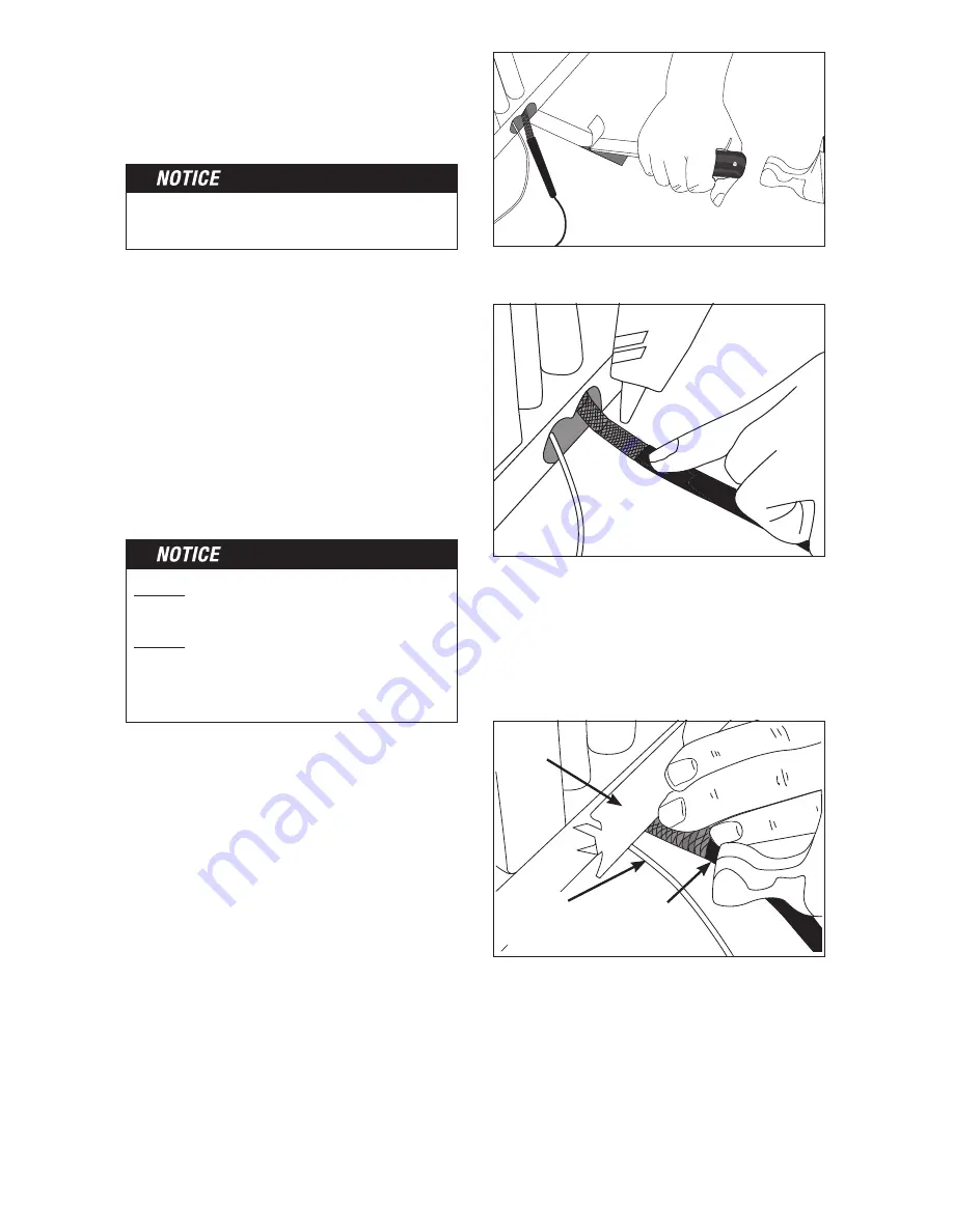
Feed the power leads through the conduit
to the control electrical box, leaving at least
6"-8" of free power lead. Chisel a slot in the
floor to recess the factory splice level with the
heating wire. Secure the factory splice with hot
glue so it cannot be pulled into the conduit.
Chisel a path for the power
lead and factory splice.
Use hot glue to secure to the floor.
Place a metal nail plate over the transition point
to protect the power lead and sensor wire.
Power Lead/
Heating Wire
Connection
Nail
Plate
Floor
Sensor
Wire
Securing the mat as flat as possible will help
make a smooth surface for spreading mortar.
DO NOT
staple or apply tape over the heating
wire. Damage can result.
DO NOT
use nails, duct tape, other types of
tape, or other unapproved fasteners
to hold the heating wire or mesh
in place. Damage can result.
If the mat comes with double-sided tape
already attached, remove the liner along one
edge and press the tape down. Remove the
liner along the other edge and press the tape
down, pulling lightly on the mat to keep it flat.
Ensure all edges of the mat are secured to
the floor using double-sided tape or hot glue.
Secure as needed across the middle of the
mat to ensure the it stays flat during floor
mortar application later. Do not use staples
or anything else that will cause damage to
any waterproofing membrane.
STEP 3.6
Secure the Mat to the Floor
Lay the mat down flat. Ensure it fits well and
has no folds or large ripples.
It may be necessary to use a metal nail plate
to protect the power lead and sensor wire
as they transition into the wall. This will help
prevent nail penetrations from drywall and
baseboards trim.


