13
5-5
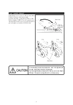
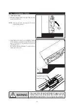
POWER OUTPUT FUSE REPLACEMENT
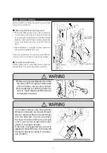
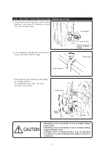
Turn Fuse Cap counter-clockwise to open. Then remove
the blown Fuse and replace it with a new one (10A,
250V).
③
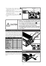
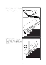
Turn on Charger's Power Switch. (Set it to )
When Red and Yellow LEDs illuminate, the
charging process will start.
④
When the charging process advances and Green
LED illuminates instead of Yellow LED, the
charging process will stop.
⑤
Turn off Charger's Power Switch. (Set it to )
⑥
Disconnect Power Plug from the 115V/230V AC
outlet.
5-4
VOLTAGE RANGE SELECTION
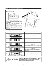
The twin power supply voltage (115VAC / 230VAC)
can be selected by setting Voltage Selection Switch.
A table of initial settings for the destination countries
is shown in the table below. Before using Charger for
the first time, be sure to check that the power voltage
is set to suit to the site's voltage.
•
Within 12 hours after Battery Charger's Green LED
illuminates (indicating Battery Pack is fully charged),
be sure to turn off Power Switch. (Set it to )
Over charging will cause deterioration of Battery and
decrease Battery capacity and shorter Battery life.
•
High temperature will be indicated on Battery Charger while
it is charging Battery Pack. Never leave any combustibles
near Charger.
ON
Power Switch
Red LED
[ Rear Panel ]
Yellow LED
(Start of charging process)
Green LED
(Completion of charging process)
[ Rear Panel ]
Power Output
Fuse (10A, 250V)
Fuse Cap
Voltage Range
115
230
Charger
AREA / COUNTRY
NORTH AMERICA
115VAC
SINGAPORE
TAIWAN
EUROPE / UK
MALAYSIA
KOREA
○
○
○
○
○
230VAC
○
○
HONG KONG
OCEANIA
○
CHINA
○

