background image


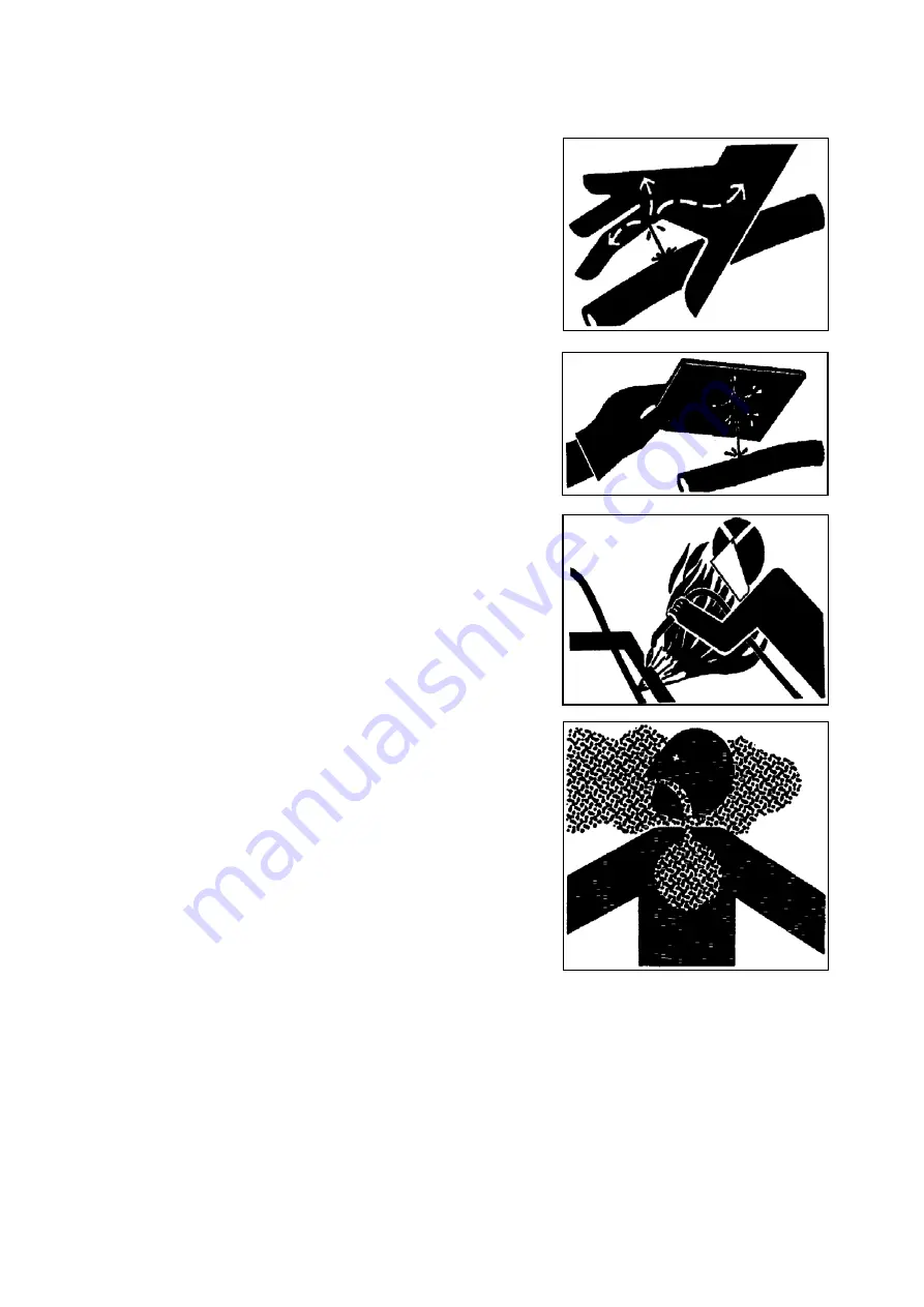
1.26 BEWARE OF INHALING FOG OR EXHAUST GAS 


Inhaling engine exhaust gas will cause disease, so 

much as, or death. 


If it is necessary to operate machine in the building, 

open door and window to ensure well ventilation, or 

use long exhaust pipe to discharge smoke. 

1.27 BEWARE OF SCALD 


During operation, engine oil, gear oil, hydraulic oil 

will become hot. Meanwhile, engine, hose, pipeline, 

and other parts will also become hot. Beware of 

scalding. 


Carry out inspection and maintenance after oil and 

parts are cooled to prevent scalding. The hydraulic oil 

tank and pipeline are high pressured, before 

maintenance or replacement, release the pressure to 

avoid hot oil erupting. 


1.28 BE CAUTIOUS OF PRESSURE LIQUIDS 


Effluent liquids in high pressure can penetrate through 

skin, causing GBH. 


Release pressure before disjoining liquids or other 

pipeline to avoid this danger. Operate control lever 

many times to release pressure. 


Before supercharging, tighten all the connections. 


Inspect leakage with cardboard, make sure to protect 

your hand and body against touching high pressure 

liquids   


If accident occurs, see the doctor at once. 


Any liquid penetrated in skin must be cleaned within a 

few hours. Otherwise it will cause necrosis. 

1.29 AVOID HEATING UP NEAR PRESSURE OIL 

PIPE 


If heating up near pressure oil pipe, the inflammable 

spray will cause severe burn to the nearby people. Don’t carry out welding, gas protection 

welding, or gas cutting near pressured oil pipe or other flammable goods. 


If it is a must to carry out welding, gas protection welding, or gas cutting near pressure oil 

pipe, mount temporary fireproof jacket to protect hose or other materials. 

1.30 AVOID HEATING UP INFLAMMABLE LIQUID PIPE 

Not permit welding inflammable liquid steel pipe or hose. Before welding this kind of pipe 

or hose, clean this pipe or hose completely with incombustible solvent. 

Summary of Contents for SWE20F 2019

Page 1: ...Operation Maintenance Manual SWE20F Hydraulic Excavator SUNWARD INTELLIGENT EQUIPMENT CO LTD Sunward Intelligent Industrial Park Xingsha Changsha China Sept 2019...

Page 2: ...ts procured from Sunward are to be used To use parts of poor quality will be detrimental to machine s overall performance All operation described in this instruction manual should be carried out exclu...

Page 3: ...SAFE MAINTENANCE 5 1 18 SUPPORT MACHINE CORRECTLY 6 1 19 CLEAN TRASH ON THE MACHINE 6 1 20 PREVENT BATTERY FROM EXPLODING 6 1 21 STORE PARTS SAFELY 7 1 22 PREVENT SPLASHING OBJECTS 7 1 23 PREVENT PAR...

Page 4: ...NVIRONMENT 31 3 2 RUNNING AND OPERATION 31 3 3 OPERATE ENGINE 32 3 4 TRAVEL CONTROL 36 3 4 1 CONTROL TRAVEL WITH PEDAL 36 3 4 2 TRAVEL WITH HANDLE CONTROL 37 3 4 3 TRAVEL SPEED 38 3 4 4 TRAVEL BRAKE 3...

Page 5: ...STORAGE 84 6 TROUBLE SHOOTING 87 7 SPECIFICATIONS 91 7 1 TECHNICAL PARAMETER 7 2 TECHNICAL INTRODUCTION 93 7 3 OPERATION PARAMETER 96 8 ATTACHMENT 99 8 1 ELECTRIC DRAWING 99 8 2 HYDRAULIC DRAWING 8 3...

Page 6: ...jury 2 WARNING indicates a potentially hazardous situation which if not avoided could result in death or serious injury 3 CAUTION indicates potentially hazardous situation which if not avoided may res...

Page 7: ...g or ear cap 1 6 CHECK MACHINE BEFORE START UP Before starting machine every day or every shift check the machine according to the contents in Check machine before start up in this manual 1 7 ADJUST O...

Page 8: ...ng confirm that the operation of traveling pedal control lever is corresponding with the traveling direction Treadle the foreside of traveling pedal or push traveling lever forward and the machine wil...

Page 9: ...ground of working site is hard enough to support machine When the machine works at pithead the tension wheel end should be outward pithead keeping the traveling orientation vertical with pit cliff In...

Page 10: ...e away from other machines at proper distance 1 16 PARK MACHINE SAFELY Stop machine as following schedule Place machine on horizontal ground Lower the bucket to the ground Run engine at low rev for 3...

Page 11: ...If the machine or work device have to be lifted for maintenance purpose the machine or work device should be well supported Don t support the machine on slag hollow brick or other fragile objects Don...

Page 12: ...RTS Touching transmission parts may cause GBH When work around the transmission parts in order to avoid accident prevent hand foot hair and clothes from entangling in the machine 1 25 AVOID INHALING A...

Page 13: ...er pipeline to avoid this danger Operate control lever many times to release pressure Before supercharging tighten all the connections Inspect leakage with cardboard make sure to protect your hand and...

Page 14: ...eing added fuel Add fuel at outdoor site Don t put oil containing rags on machine to ensure machine is clean 1 33 DISPOSE OF CHEMICAL SAFELY Touching deleterious chemical directly will cause serious i...

Page 15: ...ammer hung on the wall in cabin to break the window with emergency exit mark to leave the machine The cabin safety structure can not be repaired after damage but it can be replaced with other qualifie...

Page 16: ...nt and excessive shakes Adjust the speed and choose the best journey during the machine travelling avoid as much as possible uneven journey or the impact with possible obstacles so to minimize the vib...

Page 17: ...eration The lifting capacity is based on the criteria of the machine being level on a firm supporting ground When the machine is operated in conditions that deviate from these criteria e g on soft or...

Page 18: ...ng Rubber crawler Closed cab 1940 With swing Rubber crawler Open cab 1840 Note The above weight figures are measured with the following five requirements 1 Diesel oil tank is full diesel oil instrumen...

Page 19: ...4 Middle hood 5 Cab operation platform 6 Traveling motor 7 Support wheel 8 Carrier board 9 Rubber crawler 10 Guide wheel 11 Dozer blade 12 Dozer cylinder 13 Bucket 14 Link rod 15 Swing arm 16 Bucket c...

Page 20: ...lot safety rod 11 Assisting control pedal 12 Right traveling control rod 13 Arm swing control pedal SIMPLE CABIN 1 Monitor 2 Heating defrost alternation switch 3 Right operating handle 4 Bulldozer con...

Page 21: ...5 1 Automatic idling indicator 2 Working Light indicator 3 Engine oil pressure warning indicator 4 Work hour meter 5 Engine speed meter 6 Electric charging indicator 7 High speed traveling indicator 8...

Page 22: ...sure is low and meanwhile buzzer will warn 4 Work hour meter The number on this device is the work time of this machine 5 Engine speed meter The speed of the working engine 6 Electric charging indicat...

Page 23: ...tton the working light comes up 15 Screen switch button Press this button the screen will show the working hour and speed press the button again it will show the time 16 Fuel level indicator This indi...

Page 24: ...on green lamp turns on heater works the whole cabin starts to be heated 4 transfer switch Up and down switches are used to control dozer blade and the extension and retraction of chassis separately 5...

Page 25: ...an rotates at high speed 2 7 RADIO Well known brand radio with strong aseismatic and dustproof capability is beautiful and durable Refer to the radio user manual For the heating system adopts engine c...

Page 26: ...ut up the adjustment knob by your hand then pull or push knob C forward or backward to the proper position you want and then release the knob the slider will lock automatically 2 Backrest adjustment P...

Page 27: ...he machine meets the requirements of EN ISO 7096 2000 2 9 PILOT SAFETY LEVER When pull the safety lever up to lock position the whole front work device will not be able to work Push the safety lever t...

Page 28: ...ket swing boom swing and dozer undercarriage extending A Right joystick This joystick can make the following operations a Lift boom b Lower boom c Load backhoe or bucket close d Unload backhoe or buck...

Page 29: ...ore operating the traveling control lever Reverse the control lever when the dozer is at the heel of operator s seat The traveling control lever can operate the machine go forward or backward or chang...

Page 30: ...position then the front window is fastened Before closing the front window firstly loosen the lock pin grasp the 2 handles with your hands lower the front window slowly to the bottom then lock the loc...

Page 31: ...E CUP 8 2 703101010001 GREASE CUP 10 3 720211000008 FUSE PLATE 1 4 720211000009 FUSE PLATE 5 5 720211000010 FUSE PLATE 1 6 720211000011 FUSE PLATE 1 7 720211000018 FUSE PLATE 2 8 750401000009 GREASE G...

Page 32: ...0115000004 DOUBLE OPEN END WRENCH 1 14 740115000024 DOUBLE OPEN END WRENCH 1 15 740115000007 DOUBLE HEAD WRENCH 1 16 740106000014 SPLINE END WRENCHES 1 17 740106000016 SPLINE END WRENCHES 1 18 7401060...

Page 33: ...nning until you are familiar with the sound and feelings of new machine Operate the machine with the engine power limited in the range of 80 of the full load Avoid excessive engine idle Check the indi...

Page 34: ...ly inspection 1 Electric system Check whether there are abraded or cracked wire and slack connector or not and check whether the light can be turned on or off normally 2 Boom arm bucket dozer blade sh...

Page 35: ...filter When indicator light comes on it means that you should maintain or replace filter core Oil level in hydraulic oil tank Hydraulic oil filling mark 750610020201 Please pay attention to the follow...

Page 36: ...l lever locked 2 Turn key switch to ON position 3 Beep horn to warn surrounding people 4 Start engine by turning key switch clockwise to START position Release key the switch will return to ON positio...

Page 37: ...to right turn to START position to start engine switch will automatically return to ON position when release key Adjust engine rev When accelerograph handle is lifted to upmost and engine runs at ful...

Page 38: ...hen connecting with excavator framework keep as far as possible away from the battery connection wire end Start engine 2 Separate assistant battery First break black cathode wire away from framework D...

Page 39: ...pedal 4 backwards and treadle left pedal 1 forward FIG 3 6 4 Turning with one side crawler FIG 3 11 Turn left treadle right pedal 2 forward FIG 3 8 Turn right treadle left pedal 1 forward FIG 3 8 3 4...

Page 40: ...turning while backing as possible as you can Travel direction mark 3 4 3 TRAVEL SPEED When the machine is traveling press high low speed switch on control panel FIG 2 5 the shift of travel motor high...

Page 41: ...tual working area conditions are poor the machine s stability might be lower When traveling on slopes or grades lower the bucket to a height of 20 to 30cm In emergencies lower the bucket to the ground...

Page 42: ...round to block the machine and then restart the machine 7 The machine must travel in the pose shown in fig 3 17 when traveling up on a slope of 15 or more 8 The machine should travel at low speed and...

Page 43: ...ddershins f Make the superstructure slew clockwise g Extend arm h Retract arm Composite movement of excavator 1 When the machine slews you can operate the composite movement of boom and bucket 2 It ca...

Page 44: ...e not permitted to stand on the machine or within the range of 6 m away from working radius When begin to work or transport with full load operator should ring horn to warn 4 Bucket should dig along t...

Page 45: ...ion for 5 minutes 4 Turn ignition key to OFF position and take out key 5 Pull pilot control lever to lock position 6 Lock all doors and compartments 7 Inspection after the engine is stop Check the oil...

Page 46: ...ing area should be hard enough to prevent excavator from going down 2 The water flow should be slow 3 Undercarriage immerged height should not exceed chain support wheel 4 Avoid immerging slewing supp...

Page 47: ...l road 2 Apply boom arm and bucket generally As the figure shows place bucket and arm on a line basically Operate arm in while lifting boom slowly Once arm passes the vertical position lower boom slow...

Page 48: ...igging length and depth every time to ensure every digging is fully loaded The rapid circulation output of every full load of digging will be bigger than part full load In order to increase throughput...

Page 49: ...the machine Dozer blade operation mark Pay attention to the dozer blade position 1 When extend dozer blade it may collide with boom cylinder or bucket please pay attention to it 2 When carries out dee...

Page 50: ...onnect sling chain to the bucket teeth objects otherwise it will damage dozer blade or crawler system 3 When the machine is traveling dozer blade can t hook any object otherwise it will damage dozer b...

Page 51: ...t 3 7 HYDRAULIC BREAKING OPERATION Hydraulic breaking operation tips if equipped Choose hydraulic breaker with correct dimension and weight Consult with your dealer Pump Main valve section assignment...

Page 52: ...ately The pressure change of breaker accumulator or damaged accumulator will cause unusual hose jump and damage hydraulic breaker or machine 6 When retract foreside attachment don t allow the chisel o...

Page 53: ...to the lock position when it is not used If not if any controls should be touched accidentally when the pedal has not been locked it may cause serious accident Hydraulic breaker operation time percen...

Page 54: ...e right shows the maximum swing distance of boom swing from superstructure central line 4 MAINTENANCE 4 1 CORRECT MAINTENANCE AND INSPECTION PROCEDURE Please read this manual carefully and learn how t...

Page 55: ...ry out all recommended maintenance in this manual Check work calculagraph hour meter usually Determine when the machine needs periodic maintenance according to calculagraph Use recommended fuel hydrau...

Page 56: ...l ground 2 Lower the bucket to the ground 3 Operate engine at low rev for 5 minutes 4 Stop engine and take out the key from switch If it is necessary to maintain the machine as the engine runs operato...

Page 57: ...m if necessary 2 Make sure to check all hoses periodically and replace them if necessary 3 Consult your dealer about how to replace hose correctly Recommended periodic hose placement list Periodic rep...

Page 58: ...ex Grease EP2 Mobil petroleum Mobilux EP2 Germany 2 lithium grease Shell Shell Alvania EP Grease 2 Remark Heavy duty lithium grease Note The excavator departed from factory has been filled with marked...

Page 59: ...The excavator departed from factory has been filled with marked engine oil Engine oil specification Be sure engine oil being used must meet following criterion or classification API classification CD...

Page 60: ...nded oil Replace engine oil The engine oil and oil filter must be replaced after the first 50 hours operation After first replacement please carry out replacement as per YANMAR operation and maintenan...

Page 61: ...make it too tight to prevent screw thread distortion or filter core seals damaging 15 Open oil filter cover and fill recommended oil in engine 15 minutes later check whether the oil level lies within...

Page 62: ...ug check oil level 7 If necessary fill the filler through oil filler hole to the level as the right figure shows refer to gear oil blank In the figure is the reducer oil filler hole is the oil drainag...

Page 63: ...ion 10 for the winter only do not use kerosene Fueling 1 Refer to stop engine chapter park the excavator properly and turn off the engine correctly 2 Check fuel indicator on monitor do fueling work if...

Page 64: ...yday Shut off engine in a correct manner Open the vent valve on the bottom of the segregator Screw the valve anticlockwise for circles until the valve goes down for 25mm Vent the water in the catch ba...

Page 65: ...r and leakage of fuel hose Replace or fasten the hose if any abnormality is found refer to the table below Inspection of hoses interval hour Check point abnormality Solution Everyday Hose end Hoses wi...

Page 66: ...0L 4 Clean oil inhaling filter 5 Replace oil inhaling filter When replacing hydraulic oil 6 Clean oil returning filter 7 Replace oil returning filter core 8 Replace pilot oil filter 9 Check hose and p...

Page 67: ...and maintaining the traveling and slewing circuit at slope 7 When connecting hydraulic hoses and pipes pay special attention to keep seals surface clean and avoid damaging them Please remember followi...

Page 68: ...t key switch 6 Pull pilot control lever to lock position 7 Open right side door check oil level meter The oil level must lie between marks Otherwise you should fill oil Fill oil 1 Screw anticlockwise...

Page 69: ...der extends completely to fix excavator and park the machine on level ground 3 Lower the bucket to ground 4 Run engine at low revs for 5 minutes 5 Stop engine and take out key 6 Pull pilot control lev...

Page 70: ...rom point A to the oil tank Keep the oil level reach the position between the marks of oil level meter 9 Screw down screw plug of air vent hole Exhaust air 1 Release exhaust plug of hydraulic pump 2 O...

Page 71: ...nd connector crack crack out coming of enhanced material parts protrusion bending distortion and eroding replace replace replace replace replace replace adopt proper bending semidiameter replace FIG 4...

Page 72: ...e for 5 minutes 4 Stop engine and take out key switch 5 Pull pilot control lever to lock position 6 Open engine cover Remove pothook of Please use the original components of sunward only Only clean ai...

Page 73: ...ter core check the filter core replace it immediately whether any hole or spot is detected 14 Remove the cloth or adhesive tape of step 10 15 Install filter core 16 Install dust collection cup keep th...

Page 74: ...heated Use 50 water and 50 glycol antifreeze the engine can operate at the 37 perennially Only maintain in the first inspection When the machine is delivered 30 of antifreezing fluid has been filled i...

Page 75: ...g door and hood cover Use compressed air less than 0 2MP or water to clean or wash the radiator of oil cooler Lax fan belt may cause insufficient power of battery engine overheat and quick abnormal be...

Page 76: ...n job 10 Start engine and run it idly exhaust air shut off Shut off engine and cool down the machine before operation The body muffler radiator and other parts of the machine will be very hot when the...

Page 77: ...When necessary 6 Clean track mechanism When necessary 7 Bolt nut fasten moment When necessary Check bucket teeth 1 Check the abrasion and laxation of bucket teeth everyday 2 Replace the seriously abra...

Page 78: ...5 Calibrate the arm and new bucket ensure the bucket will not to roll 6 Fit pin A and B and fit corresponding orientation pins and new clip springs 7 Adjust bucket connection clearance of pin A and B...

Page 79: ...ubber dustproof of control lever B Link bar mechanism 1 Remove rubber mat 2 Loosen the bolt disassemble cover 3 Disassemble rubber dustproof 4 Use doper to add lubricant to lubricant nozzle 5 Clean th...

Page 80: ...pressure relief valve may fly out and cause damage if you do not operate as the follow procedures Slowly screw off the grease pressure relief valve Never let your body face legs or arms be exposed in...

Page 81: ...eplacement 1 If the track has been pulled longer and can not recover it should be replaced immediately 2 If the dummy club is lower than 5mm replace track 3 If more than 2 of the steel wire core have...

Page 82: ...that it is in mesh with sprocket wheel and guild wheel 6 Tighten the rubber track with tightening mechanism until it reaches the standard tensity 7 Install the other track in the same manner Clean th...

Page 83: ...0 9 8 0 5 12 13 M8 1 25 22 6 1 1 14 17 M10 1 5 47 1 2 4 17 19 M12 1 75 83 4 4 1 19 22 M14 2 0 134 4 6 7 22 24 M16 2 0 207 9 10 4 27 30 M20 2 5 410 9 20 5 Thin screw thread 12 13 M8 1 0 24 5 1 2 14 17...

Page 84: ...the radiator and oil cooler cooling fin to remove dust and dirt 3 More frequently clean the fuel sucking filter and its core 4 Termly carry out clean maintenance especially the surface of the engine a...

Page 85: ...to the parts which need this And smear a layer of oil Battery Take off the battery and charge it then restore it Coolant Add antirust Add antifreeze if it is possible to be frozen or vent out all the...

Page 86: ...e width cabin 1170 mm There is a possibility that the machine will roll tip over or fall while loading or unloading it Therefore you need to take the following precautions Select a firm level surface...

Page 87: ...ce backward at the rear and travel backward 4 Line up the center of the truck bed with the center of the machine and the center of the ramps with the center of the crawlers 5 Use the engine accelerogr...

Page 88: ...achine While storing the machine retract the cylinder piston rod to the inside of cylinder as much as possible to avoid piston rod corrosion caused by rain and wind clean machine surface and all the e...

Page 89: ...ation handle for several circles Machine storage period 1 Run the machine once a month during storage period 2 Run the air conditioner system once a month Machine handling after storage 1 Wipe the gre...

Page 90: ...d floats in pilot control pipeline and hydraulic cylinder etc 2 No pressure or exceeding pressure in pilot system 3 Low hydraulic oil temperature and high viscidity of hydraulic oil 4 Hydraulic pump m...

Page 91: ...onding pilot valve malfunction 2 Hydraulic motor malfunction 3 Slewing retarder malfunction 4 Slewing bearing malfunction 5 Need to add lubricant grease into the slewing bearing 1 Repair 2 Consult wit...

Page 92: ...ion of the cubage efficiency 3 Overfall valve and over load valve opens too frequently 1 Clean 2 Contact the dealer 3 Over digging over loading change the digging method Some unexpected actions occur...

Page 93: ...the boom arm bucket and flat swing through 2 control joysticks Left operate handle model HC RCX 47585 Right operate handle model HC RCX 47586 Pilot system pressure 3 5Mpa Hydraulic cylinder standard...

Page 94: ...uel tank capacity 23L Travel mechanism Speed ratio 31 Maximum output torque moment High speed 898 N m Low speed 1589Nm Travel speed High speed 3 6 km h Low speed 2 1 km h Gradeability 30 Travel brake...

Page 95: ...ydraulic pump main valve drive motor and swing motor from Italy Nachi HC with perfect quality and stable work condition can ensure the stable work of the whole system Full power qualified system can m...

Page 96: ...iently tension and loosen track The helix spring provides huge tension power for oriented wheel and ensures the track orientation avoid track digression High alloy steel track has good adhesion stabil...

Page 97: ...it is very easy to recognize the indicators on it such as engine electronic device and hydraulic system All the indicator s sketch maps comply with SAE certification There is radio installed in cabin...

Page 98: ...stance between wheel mm 1210 B Length of track mm 1555 C Turret distance to ground mm 482 D Gyration radius of turret mm 1122 E Chassis width mm 990 1360 F Track width mm 230 G Ground clearance of cha...

Page 99: ...770 B Max unloading height mm 2720 C Max digging depth mm 2380 D Max vertical digging depth mm 1870 E Max digging radius mm 4040 F Max reach at ground level mm 3945 G Max lifting height of dozer mm 29...

Page 100: ...should be fully acquainted with the operator s manual and the operating safety manual furnished by the manufacturer before operating the machine NOTE 1 Lift capacities shown are without the power boos...

Page 101: ...99 8 ATTACHMENT 8 1 20FNELECTRIC DRAWING...

Page 102: ...100 8 2 20FHYDRAULIC DRAWING...

Page 103: ...wing motor 14 arm cylinder 5 left joystick pilot control valve arm swing 15 boom cylinder 6 right joystick pilot control valve boom bucket 16 bucket cylinder 7 selector valve blade crawler extends and...

Page 104: ...ess 16 LiXiang Road Xingsha economic and technologic development district Changsha Hunan Tel 0086 0731 83572739 83572783 Maintenance point our office in some provinces and cities of China About distri...

Reviews: