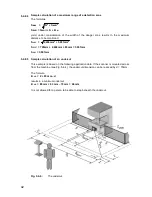
39
5.4.8.1 Additions and minimum depth of detection zone
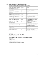
The sum of the system-specific and application-specific detection zone additions (see
Chapter 5.3.5) is calculated according to the following formula:
Z
TOT
= Z
SM
+ Z
REFL
+ Z
AU
Z
TOT
= Sum of the system-specific and application-specific detection zone additions,
in mm
Z
SM
= Scanner measurement error, in mm
Z
REFL
= Addition of the reflectors taken into account, in mm
Z
AU
= Addition for application-specific undercut, in mm
The depth of the detection zone, with reference to the direct distance between the danger
zone and the detection point or line, is calculated according to the following formula:
S
T
= (K × (T
SCAN
+ T
MACH
+ ( T
LAG
× L
LAG
))) + C + Z
TOT
S
T
Depth of detection zone, distance from danger area to detection point or line,
including system and application-specific additions, in mm
K
Approach speed of a person or a person’s body parts (1,600mm/s), in mm/s
T
SCAN
Response time of the scanner, in s
T
MACH
Response time of the machine or system, in s
T
LAG
Lag time of the entire system, in s
L
LAG
Factor for increase in lag time
C
Safety-related constant, in mm
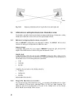
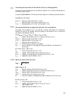
5.4.8.2 Maximum
range of detection zone
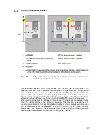
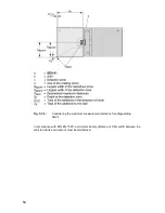
S
BDIFF
= G
BDIFF
+ S + Z
S
MAX
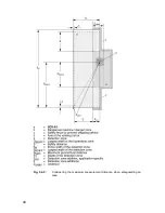
Maximum range of the detection zone considering the diagonals, in mm
S
T
Depth of the detection zone, in mm
S
BDIFF
Largest width of the detection zone between the axis of the rotating mirror
and the outer edge of the detection zone, in mm
G
BDIFF
Largest width of the danger zone between the axis of the rotating mirror and
the boundary of the danger zone, in mm
S
Safety distance, minimum distance from the danger zone to the point of
detection, to the plane of detection, or to the detection zone, in mm
Z
Required detection zone additions, in mm
S
MAX
S
T
2
+ S
BDIFF
2
=
=
=
=
=
=
=
=
=
=
=
=
=
=
Summary of Contents for SD3-A1
Page 1: ......
Page 12: ...12...
Page 40: ...40 Fig 5 4 5 Considering the maximum measurement distance when safeguarding an area...
Page 60: ...60 Fig 6 2 1 Example of a zone pair changeover for an AGV on a curved route...
Page 61: ...61 Fig 6 2 2 Example of zone pair changeover with combined with reducing speed of the AGV...
Page 101: ...101 13 13 Dimensional drawings of the SD3 A1...
Page 102: ...102 13 14 Dimensional drawings of the mounting system...
Page 106: ......

