51
5.7.6 Additions
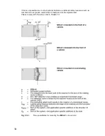
The axis of the rotating mirror (midpoint of the scanner) is of critical importance when
configuring the detection zones. This axis is assigned a value of 64mm from the front
edge of the scanner when calculating detection zones.
Add
83mm
or
100mm
for the maximum radial measurement error Z
SM
as described in
Chapter 5.3.5.
Add an addition Z
REFL
as described in Chapter 5.3.5 if reflectors could be present in the
area.
Without information from the AGV manufacturer, take into account the wear and tear on
the brakes by adding an addition L
STOP
of at least 10% of the braking distance, as long as
this is not already included in the braking distance S
STOP
.
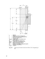
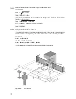
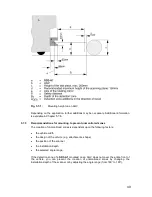
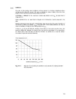
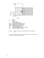
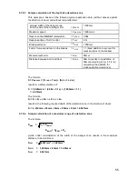
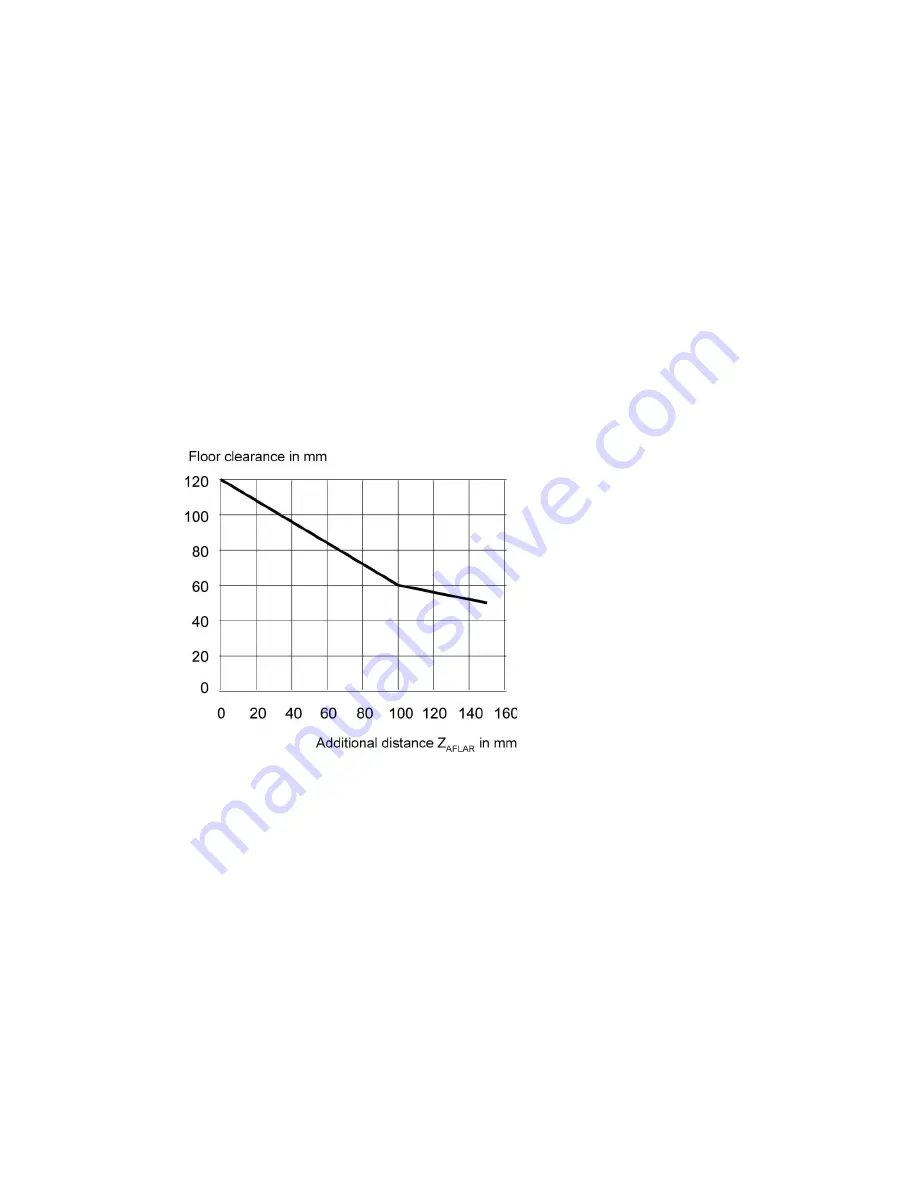
If there is a very small distance between the bottom of the AGV and the floor, the
detection difference between the leg and the toes must be considered in the calculation.
For AGVs with a floor clearance of less than 120mm, an addition Z
AFLR
must be added.
This refers only to the travel of direction.
Fig. 5.7-3:
Diagram for calculating the addition to compensate for inadequate AGV
floor clearance
Summary of Contents for SD3-A1
Page 1: ......
Page 12: ...12...
Page 40: ...40 Fig 5 4 5 Considering the maximum measurement distance when safeguarding an area...
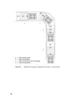
Page 60: ...60 Fig 6 2 1 Example of a zone pair changeover for an AGV on a curved route...
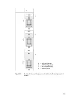
Page 61: ...61 Fig 6 2 2 Example of zone pair changeover with combined with reducing speed of the AGV...
Page 101: ...101 13 13 Dimensional drawings of the SD3 A1...
Page 102: ...102 13 14 Dimensional drawings of the mounting system...
Page 106: ......

