64
7.5
OSSD 1 (X1-12) and OSSD 2 (X1-11)
When the detection zone is interrupted, the two semiconductor outputs switch OFF and,
by way of elements such as positively guided relays, cause the monitored machine(s) to
shut down.
It is not admissible to control different safety circuits with a single OSSD. Connected
loads must exhibit a low-pass behavior in accordance with the plausibility control
conducted by the scanner (f
g
1kHz, C
L
100nF). The OSSDs are equipped with
an
internal electronic current limit to protect them against damage from overload.
For some sample connections, see Chapter 8.
7.6
Data communication
The interface X2 allows the
SD3-A1
to support two types of connections to the PC.
Communication via the X2 connector in RS-232 mode does not require any further
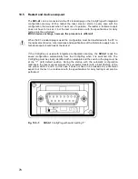
bridging. To enable data transfer in RS-422 mode, connect pin 5 with pin 6. The scanner
automatically adjusts itself to the appropriate transfer type and baud rate.
The interface (X2) is used for
Guard operation is only permitted with the PC cable (X2) or dummy connected screwed
ON. This also applies for transport and storage.
Please note the pin assignments specified in Chapter 9.5. For additional information on
using the X2 interface, refer to the instruction manual (software operation) for the
program “
SD3SOFT
”.
8
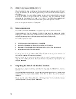
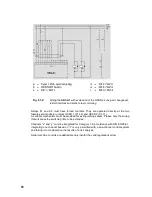
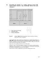
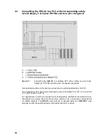
Integrating the SD3-A1 into Machine Controls
The following examples illustrate possibilities for integrating the
SD3-A1
into machine
controls.
Once the operating voltage pin X1-3 (+U
B
) has been connected to pin X1-1 (GND) and a
detection zone has been activated (X1-4, X1-6, X1-7 or X1-8), the unit is ready for
operation.
Please see the point “Define Detection / Warning Zones” in the instruction manual
(software operation) for the program “
SD3SOFT
”.
x
configuring and setting parameters for the
SD3-A1
x
transferring measurement data while the scanner is in operation
x
evaluating the coordinates during parameter setting (e.g. for AGV applications)
x
advanced status and control diagnostics.
Summary of Contents for SD3-A1
Page 1: ......
Page 12: ...12...
Page 40: ...40 Fig 5 4 5 Considering the maximum measurement distance when safeguarding an area...
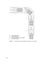
Page 60: ...60 Fig 6 2 1 Example of a zone pair changeover for an AGV on a curved route...
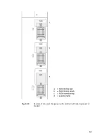
Page 61: ...61 Fig 6 2 2 Example of zone pair changeover with combined with reducing speed of the AGV...
Page 101: ...101 13 13 Dimensional drawings of the SD3 A1...
Page 102: ...102 13 14 Dimensional drawings of the mounting system...
Page 106: ......

