70
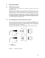
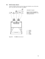
The connector adapter of control cable X1 must be connected with interface X1 and
screwed tightly to the
SD3-A1
. The connector adapter of cable X2, or else the X2 dummy
cap (without a cable), must also be screwed tightly to the
SD3-A1
. Screw thread bolts are
located on the top of the scanner housing for this purpose. If one of the two connection
housings is missing, the
SD3-A1
no longer meets the requirements of protection type 65.
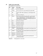
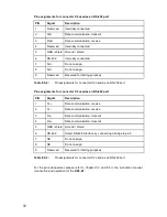
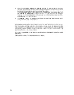
For information on the assignment of the connector, please refer to Chapter 2.2 and 9.5.
9.3 Connector
assembly
Every connector adapter consists of the following individual parts:
9.4
Points to consider when preparing and laying the cables
Scanner control cables may not be laid in a stand parallel to power supply cables for
machines. This minimizes the effects of inductive interference factors from motors
carrying high current. In addition, the cables should be laid so that they cannot be
damaged (e.g. by being crushed or pinched).
Cabling prepared for connection to the scanner is available as an optional accessory in
various lengths and for both interfaces. For further information, see Chapter 13.
x
Housing with sealing ring and fastening nuts
x
Cable screw coupling (M16) with dummy plugs
x
Sub-D9 connector and / or Sub-D15 jack, each with a solder connection
x
The cross-section of cable X1 must be at least 0.5mm
2
.
x
The outer diameter of the cable must be between 6.5mm and 10mm.
x
The maximum cable length for X1 is 50m.
x
The maximum cable length for X2 is 10m (for RS-232).
x
The maximum cable length for X2 is 50m (for RS-422, twisted pair).
x
Use shielded cables.
x
Connect the cable shielding with PE to the electronics cabinet only.
x
The cables must not be laid loose.
Summary of Contents for SD3-A1
Page 1: ......
Page 12: ...12...
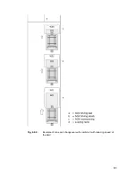
Page 40: ...40 Fig 5 4 5 Considering the maximum measurement distance when safeguarding an area...
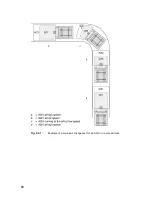
Page 60: ...60 Fig 6 2 1 Example of a zone pair changeover for an AGV on a curved route...
Page 61: ...61 Fig 6 2 2 Example of zone pair changeover with combined with reducing speed of the AGV...
Page 101: ...101 13 13 Dimensional drawings of the SD3 A1...
Page 102: ...102 13 14 Dimensional drawings of the mounting system...
Page 106: ......

