77
10.4
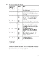
Status information of the SD3-A1
1 = LED is lit up
0 = LED is dark
– =
Undefined
Table 10.4-1:
Status information of the
SD3-A1
Upon delivery, the
SD3-A1
is programmed with the largest possible detection zone and
with activated startup interlock and manual restart. For this reason, LED 5 is constantly lit
up when the scanner is switched ON. When starting up your
SD3-A1
, please modify the
parameters to meet the specific needs of your application.
Scanner display
LED numbers
1 2 3 4 5
Indicator
Status
– – 1 0 –
LED 3
The OSSD outputs are switched OFF
(e.g. during booting).
1 0 0 1 0
LED 1
LED 4
The sensor function is active (measurement
operation without an interruption of the
activated zone pair). The OSSDs are switched
“active high”.
1 1 0 1 0
LED 1
LED 2
LED 4
The sensor function is active (measurement
operation without a violation of the activated
detection zone). Violation of the activated
warning zone. The OSSDs are switched
“active high”.
0 1 1 0 –
LED 2
LED 3
Violation of the warning zone. Violation of the
detection zone. The OSSDs are switched OFF.
1 0 0 1 (1)
LED 1
LED 4
LED 5
The sensor function is active (measurement
operation without a violation of the activated
detection zone). The OSSDs are switched
“active high”. Warning message signaled by
slow flashing at approx. 2Hz (e.g. with optical
window dirty)
0 0 1 0 (((1)))
LED 3
LED 5
The OSSDs are switched OFF.
Fault message indicated by fast flashing at
about 4Hz (e.g. with defect or safety-related
fault)
1 0 1 0 1
LED 1
LED 3
LED 5
The sensor function is active (measurement
operation without an interruption of the
activated zone pair).
The OSSDs are switched OFF. Restart
interlock is active.
0 1 1 0 1
LED 3
LED 5
Interruption of the zone pair.
The OSSDs are switched OFF.
Restart interlock is active.
Summary of Contents for SD3-A1
Page 1: ......
Page 12: ...12...
Page 40: ...40 Fig 5 4 5 Considering the maximum measurement distance when safeguarding an area...
Page 60: ...60 Fig 6 2 1 Example of a zone pair changeover for an AGV on a curved route...
Page 61: ...61 Fig 6 2 2 Example of zone pair changeover with combined with reducing speed of the AGV...
Page 101: ...101 13 13 Dimensional drawings of the SD3 A1...
Page 102: ...102 13 14 Dimensional drawings of the mounting system...
Page 106: ......

