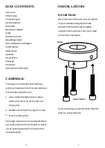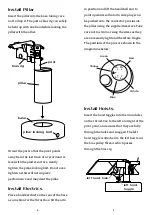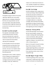
hold the nut in position inside the arm tube
to receive the countersunk M3 bolt. Once
the nut and bolt have engaged, insert a flat
screwdriver end between the nut and the
inner wall of the arm tube to lock the nut so
that you can tighten the bolt. Do not over-
tighten as this could damage the fragile
carbon-fibre arm tube.
Set Bias
The bias force (also known as ‘anti-skate’) is
adjusted in three ways.
First, the difference between applied bias at
the start and end of the record is adjusted
by shortening or lengthening the bias
pulley. Bias force varies more between the
rotor’s 11 o'clock and 12 o'clock positions
than between 9 o'clock and 10 o'clock.
Shortening the pulley will increase the
range of applied bias. To shorten it, pull at
the loose end when the arm is at rest.
Lengthen it by cuing the arm beyond the
last track of the record or further.
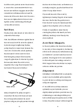
Always lengthen the pulley enough to
ensure that the bias rotor does not reach
the vertical position before the end of
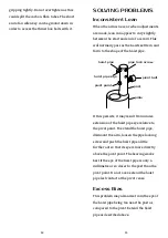
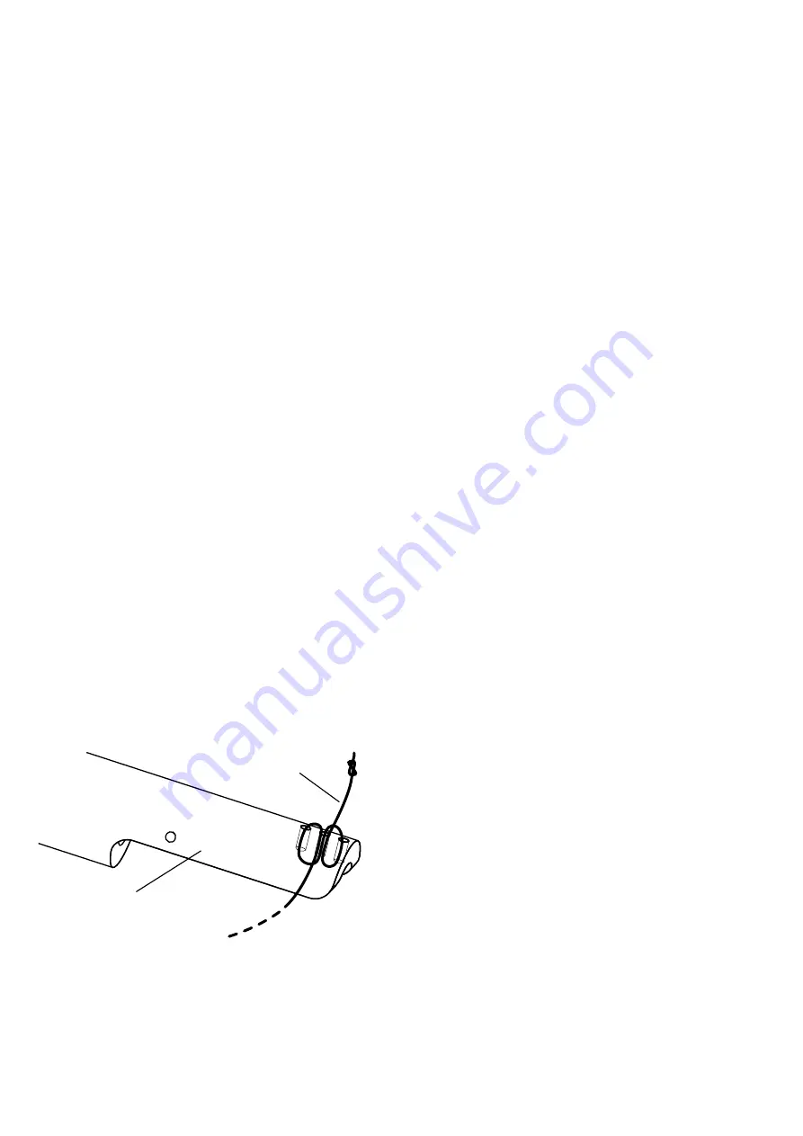
playback. A figure-of-eight pattern through
10
bias rotor
bias pulley
the bias rotor’s three holes, as illustrated, is
normally enough to grip the bias thread but
allow it to slip when forced.
The overall amount of bias is set by
tightening or loosing the grub screw inside
the rotor. The further the grub screw is
from the rotor’s axle, the more bias will be
applied. Do not tighten as far as the axle.
Finally, it is possible to adjust bias by
rotating the pillar in the base if you have
difficulty reaching correct bias by the
above methods.
Arm-Rest Magnets
In the rest position the thrust box attaches
to one, two, or three magnets in the bias rig,
which can be advanced or withdrawn using
a screwdriver to achieve a stable arm-rest
position. One magnet in the outer position
is often adequate, but adding a second or
third magnet in the other holes can help to
achieve a stable rest position.
Alignment
SUPATRAC’s ‘SUPATRACTOR’ is included to
make it easy to establish optimal spindle-
to-pivot distance, cartridge overhang and
null point alignment.
If it is difficult to set these distances
optimally on your turntable, you can
slightly adjust spindle-to-pivot distance by
withdrawing or extending both the pivot
bolt and hoist pipe in equal measure. If this
is done, the pillar and post will no longer be
11


