background image


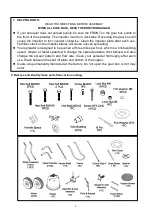
PARTS LIST 


Ref# 

Description 

Qty 

Ref# 

Description 

Qty 

Handle Spacer 

27 

Shut off plate 

Carriage Bolt M6x25 

28 

Big Flat Washer Ø4 

Teeth Washer Ø8 

29 

Screw ST4.2x12 

Gauge & Lever Assembly 

30 

Frame   

Adjust Handle Pole 

31 

Frame Brace 

Adjust Handle A 

32 

Hex Bolt M6X60 

Adjust Handle B 

33 

Hex Bolt M6X35 

Screw ST4.2x18 

34 

Flat Washer Ø16 

Spacer 

35 

End Cap 

10 

Wing Nut M6 

36 

Pneumatic Wheel 

11 

Hex Bolt M6x45 

37 

Inner Axle Bushing 

12 

Nylon Washer 

38 

Outer Axle Bushing 

13 

Big Flat Washer Ø6 

39 

Gear Box & Axle Assemble 

14 

Screen 

40 

Thin Washer 

15 

Handle Cover 

41 

Screw M4x20 

16 

Hopper 

42 

Impeller 

17 

R Pin Ø2X60 

43 

Screw ST6.3X40 

18 

Hopper Bushing 

44 

Hex Lock Nut M5 

19 

Pivot & Bracket Assembly 

45 

Cross Brace 

20 

Wheel Assembly Frame 

46 

Adjust Connect Rod B 

21 

Nut M6 

47 

Hex Bolt M5X45 

22 

End Cover 

48 

Flat Washer Ø6 

23 

Upper Handle 

49 

Lock Washer Ø6 

24 

Lock Nut M6 

12 

50 

Cotter Pin Ø2x10 

25 

Control Rod A 

51 

Rain Cover 

26 

Handle Shaft 


Summary of Contents for SSR50

Page 1: ...50LB SPREADER SSR50 ASSEMBLY AND OPERATING INSTRUCTION ...

Page 2: ...r to turn counter clockwise Clean the impeller plate after each use Fertilizer stuck on the impeller blades will cause uneven spreading Your spreader is designed to be pushed at three miles per hour which is a brisk walking speed Slower or faster speeds will change the spread patterns Wet fertilizer will also change the spread pattern and flow rate Clean your spreader thoroughly after each use Was...

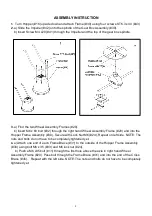
Page 3: ...y Frame 20 and into the Hopper Frame Assembly 30 Secure with Lock Nut M6 24 Repeat on left side NOTE The nuts and bolts do not have to be completely tightened yet 4 a Attach one end of each Frame Brace 31 to the outside of the Hopper Frame Assembly 30 using bolt M6 x 35 33 and M6 lock nut 24 b Push a M6 x45 bolt 11 through the first hole above the axle in right hand Wheel Assembly Frame 20 Pass bo...

Page 4: ... Axle End Cap 35 by tapping with a wooden or rubber mallet b Slip Inner Axle Bushing 37 onto the left side of the axle pushing the Inner Axle Bushing into the Outer Axle Bushing until tight Push the Wheel onto the axle Insert Flat Washer Ø 16 34 and attach Axle End Cap 35 by tapping with a wooden or rubber mallet NOTE The nuts and bolts do not have to be completely tightened yet Note Insert the In...

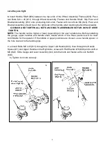
Page 5: ...DO NOT OVER TIGHTEN NOTE The handle can be higher or lower depending on the user s preference Before installing the gauge upper handles and handle shaft decide which of the three positions will be most comfortable for the operator If the middle or upper positions are chosen use a handle spacer in the hole nearest to the handle grips 7 a Insert Bolts M6 x 45 11 through the Upper Left Handle 23 then...

Page 6: ...Adjustable Handle 6 7 c Take lower nut 21 off the bottom end of the Control Rod 25 and insert rod into the hole in the Pivot and Bracket Assembly 19 d Screw nut back into place 9 Slip the threaded end of Adjustable Connecting Rod 46 into the Shut Off Plate 27 with a Flat Washer Ø6 48 then fasten with Flat Washer Ø6 48 and Lock Nut M6 24 ...

Page 7: ... the three holes match up If the holes are not properly aligned the hopper will not close completely b To operate the spreader push the handle up to the top position Adjust the wing nut as needed to regulate the flow of material passing through the spreader c Insert R Pin 17 into the hole at the top of the axle spindle at the bottom of the Hopper 16 as shown Make sure impeller is turning in the ri...

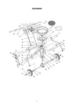
Page 8: ...8 DRAWING ...

Page 9: ... Pneumatic Wheel 2 11 Hex Bolt M6x45 7 37 Inner Axle Bushing 2 12 Nylon Washer 1 38 Outer Axle Bushing 2 13 Big Flat Washer Ø6 1 39 Gear Box Axle Assemble 1 14 Screen 1 40 Thin Washer 1 15 Handle Cover 2 41 Screw M4x20 1 16 Hopper 1 42 Impeller 1 17 R Pin Ø2X60 1 43 Screw ST6 3X40 4 18 Hopper Bushing 1 44 Hex Lock Nut M5 1 19 Pivot Bracket Assembly 1 45 Cross Brace 1 20 Wheel Assembly Frame 2 46 A...

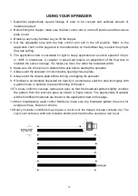
Page 10: ...roadcast width 6 Make sure the drive pin is in stalled in the axle before starting the spreader 7 Always start the spreader in motion before opening closure plate 8 Always shut the closure plate before turning or stopping the spreader 9 If fertilizer is accidentally deposited too heavily in a small area soak the area thoroughly with a garden hose or sprinkler to prevent burning of the lawn 10 To i...

Page 11: ...11 Head Office Technical Enquiries Owen Street Coalville Leicestershire LE67 3DE Tel 01530 510060 Fax 01530 510299 email info supaturf co uk info supaturf co uk info supaturf co uk info supaturf co uk ...

Reviews: