12
www.supercircuits.com
SECTION 3: INSTALLING YOUR SYSTEM
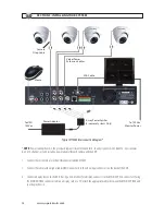
Video/Power
Extension Cables
VGA Cable
5-way Power Splitter
(4-camera Systems Only)
To 120 Vac
Monitor Power
Power Adapter
Mouse
Camera
Drop Cable
To UPS/
120 Vac
Typical SY70304 Interconnection Diagram*
*
NOTE:
Power cabling shown in the previous diagram is recommended for 4-channel systems with CD33W-2 series cameras.
8- and 16-channel systems include a power adapter for each camera and the DVR.
1. Connect the system mouse to the USB connector labeled MOUSE.
2. Connect the camera video signal cables (BNC connectors) to the video input connectors on the back of the DVR.
3. Connect a display device to the DVR. If using a VGA monitor for a display, connect it to the MAIN OUT VGA connector. If using
the MAIN OUT BNC connector to drive a display such as a TV, attach the appropriate cables between the MAIN OUT BNC and
your display device.


