background image

3

4

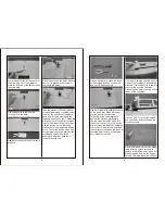
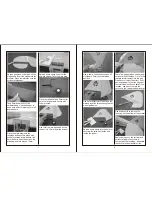
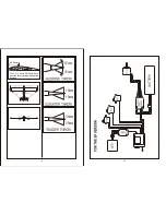
Place the servo tray on the center of
the main wing set. Use marker to 
mark the location of the servo tray on
the main wing.

Use hobby knife to remove the
covering over the hole.

Use epoxy to secure the servo tray in
position.

Place the servo on the servo tray and
secure it in place with the screws 
come with the servo.

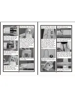
Take two pieces of 330mm rods out
of the hardware bag. Use side cutter
to cut all the parts out of the plastic
parts tree. Screw a clevis onto the
threaded end of each rod. Thread the
aileron horns onto the aileron torque
rods in the wing until the rod is flush
with the aileron horn. Attach the
clevises onto their respective aileron
horns. Center the aileron servo and
using marker to place a mark on the
unthreaded end of the aileron
pushrods where they pass their
respective servo arm.

Using z-bend pliers, make a z-bend 
at the marked location on each rod
and cut off the excess rod.

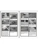
Use 2mm reamer to enlarge the hole
on the servo arm. Place a piece of
fuel tubing over the clevises.
This will provide extra insurance
against the clevises accidentally
coming open. Install the z-end into
the hole of the servo arm. Adjust the
aileron torque rod length by screwing
in or out until the aileron is exactly in
the neutral position when the servo is
centered and clevis is in the aileron
horn. Adjust both sides.

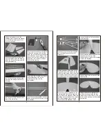
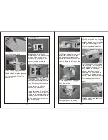
Find the pre-serving opening on both
sides of the fuselage for assembling
windows. Use hobby knife to remove
the covering over the openings.
Please reserve 6mm covering on the
edges of the openings. 

O

Use iron (140 C) to trim the edges
and use hobby knife to remove the
excess covering.

Place the window set on the working
table and use curved scissors to
remove window from the window set.
Please reserve 6mm on the edges. 
Spread UHU glue along the edges of

Summary of Contents for PIPER CUB J-3 GP/EP

Page 1: ...a toy If misused it can cause serious bodily harm and damage to property Fly only in open areas following all instructions included with your radio Before beginning the assembly remove each part from...

Page 2: ...0 3000mAh 4 cell Li Po ESC 50 60A Propeller 11x6 12x6 Aluminum spinner for EP flying Place the main wing and hinges on the working table Bend the hinges several times Spread the Super glue on the hing...

Page 3: ...spective servo arm Using z bend pliers make a z bend at the marked location on each rod and cut off the excess rod Use 2mm reamer to enlarge the hole on the servo arm Place a piece of fuel tubing over...

Page 4: ...s temporary Spread generous super glue on the hinges and insert the hinges into the rudder until the hinge line is even with the leading edge of the rudder Place the rudder onto the vertical stabilize...

Page 5: ...udder It is 35 mm from the bottom Use a sharp hobby knife to open a V slot depth 2mm on the marked position Use 2mm driller to drill a hole on the marked location for accepting the tail wheel guide wi...

Page 6: ...e 2mm driller drill hole Secure the control horns and plate in place with 2 x 15mm screws Using Z bend pliers make a Z bend at the marked spot on the rod Use 2mm driller to open a hole on the servo ar...

Page 7: ...crew too tight Screw one end of 180mm wire to the bottom of the horizontal and the other end to the tail gear Check all the wires They must be bilateral symmetry Screw the screws and washers tight to...

Page 8: ...tery Find the pre served gear slot on the bottom of fuselage Use hobby knife to remove the covering on the slot Take one piece of heat shrink tubing out of the hardware bag Cut the tubing into 5mm x 8...

Page 9: ...dges Sand the bottom side Spread epoxy to secure the plastic engine on two sides of cowling It s only one side for GP version Place the main wing on the fuselage Screw in the M4x40mm wing bolts Cut th...

Page 10: ...PS Use epoxy to secure the servo tray on the planking Apply one side of adhesive Velcro on the fuel tank and another side on the battery tray Connect the fuel tank and pressing hole with fuel tubing P...

Page 11: ...19 15mm 15mm 15mm 15mm 35mm 35mm 20 80 90mm The C G Point is 80 90mm back from the leading edge against the fuselage...

Reviews: