background image

Updated: 10 October, 2009

Page 16

REF: REI-90-0611

11.

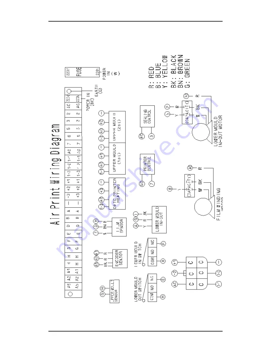
Wiring Diagram

Summary of Contents for REI-90F

Page 1: ......

Page 2: ...oroughly read this manual first CAUTION BURN HAZARD Cleaning and maintenance should be performed by your trained personnel only Allow unit to cool at least 90 minutes before normal cleaning If hot mac...

Page 3: ...on 5 4 Control Panel 6 5 Resetting Computer Program 7 6 Roll Film Set Up 10 7 Date Printer Coder 10 8 Mould Removal and Replacement 11 6 1 Upper Mould 11 6 2 Lower Mould 12 9 Maintenance and Cleaning...

Page 4: ...0L M Sealing moulds can be exchangeable for different tray for about 5 minutes only Safety Features gearless construction and safety front panel Container Photo Sensor or Manual option Film Sensor or...

Page 5: ...ld will move to the initial eject position This power on checking procedure will take approximately five seconds The sealing film system is also checked by the machine control system at all times c On...

Page 6: ...for use TEMPERATURE CONTROL This is to manage the temperature setting in degrees centigrade o C Up and Down to increase or decrease one unit of value Polypropylene PVC or PET films could have the def...

Page 7: ...heater 030 220 C 130 P 1 3 Printer heater 030 220 C 100 P2 Calculator lock open Lok Lock can t rest Opn Open can set Opn P3 Sealing time 001 030 unit 0 1sec 3 sec 010 P4 Cup waiting time 000 030 unit...

Page 8: ...position Use keys to increase or decrease the value by one unit 0 1 second Generally the value is assigned between 005 and 015 It is set at 010 1 sec at the factory This function based on the whether...

Page 9: ...and the right display will give a value between 001 199 set the correct value for the distance between the 1st printing and 2nd printing The 1st printing is operated with the sealing mould simultaneou...

Page 10: ...bbon Ribbon Color 100 meters Black standard Maximum Number of Alphanumeric per line 9 e g 20060918 EXP060918 Temperature Setting adjustable 50 100 C Default 100 ON OFF Using the Control Panel Printer...

Page 11: ...your trained personnel only Allow unit to cool at least 90 minutes before normal cleaning Always wear hot pad gloves when performing machine cleaning 6 1 Upper Mould Sealing and Cutting Function Stand...

Page 12: ...osition for the sealing and the cutting function Exchanging Simply remove the black screw from the bottom of the lower mould and pull out the lower mould 9 Maintenance and Cleaning ELECTRICAL HAZARD A...

Page 13: ...ould cylinder sensor or limited switch Top area error E E03 Limited switch error Lower mould output stop F E04 Sealing film is used up out off position or eye mark sensor error G E05 Limited switch er...

Page 14: ...mould moves out half way Check the jack up system The bearing roller may go out off the slide way E03 Lower mould system error Error for un smooth lower mould movement Clean both the slide ways and b...

Page 15: ...nsor position and clean the sensor Adjust the film roll and clamp 3 Poor sealing performance Film material is not suitable for the container The heater is not clean Sealing time is too short Cutter is...

Page 16: ...Updated 10 October 2009 Page 16 REF REI 90 0611 11 Wiring Diagram...

Page 17: ...Updated 10 October 2009 Page 17 REF REI 90 0611...

Reviews: