2-16
X8SIE/X8SIE-F/X8SI6-F/X8SIE-LN4/X8SIE-LN4F User's Manual
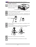
Installation Instructions
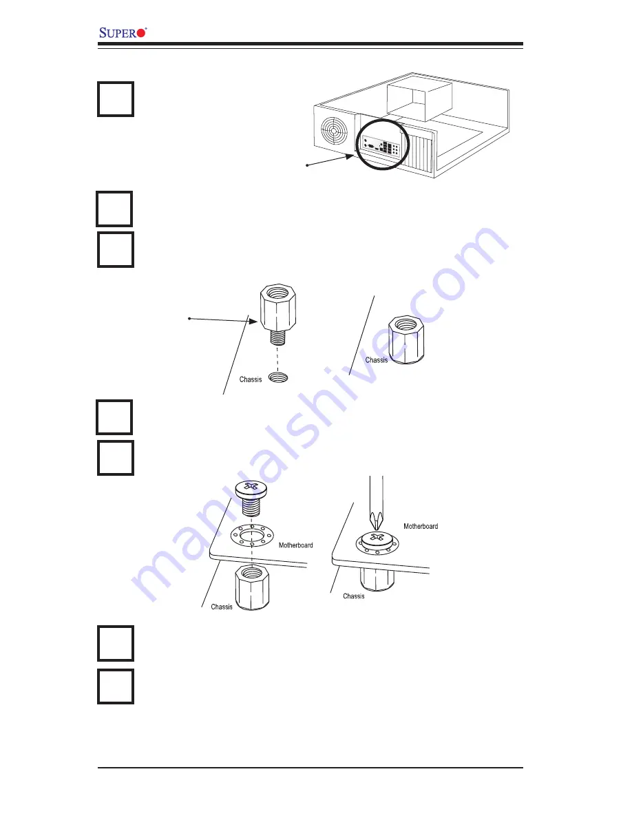
Install the I/O shield into the chassis.
Locate the mounting holes on the motherboard. Refer to the layout on the
previous page for mounting hole locations.
Locate the matching mounting holes on the chassis. Install standoffs in the
chassis as needed. Align the mounting holes on the motherboard against the
mounting holes on the chassis.
Install the motherboard into the chassis carefully to avoid damage to mother-
board components.
Insert a Pan head #6 screw into a mounting hole on the motherboard and its
matching mounting hole on the chassis, using a Philips screwdriver.
Repeat Step 4 to insert #6 screws into all mounting holes.
I/O Shield
1
2
3
Stand Off
4
5
6
Make sure that the motherboard is securely placed in the chassis.
7
Note: Image is for illustration
purposes only. Your particular
chassis may be different.
Summary of Contents for X8SI6-F
Page 1: ...USER S MANUAL Revision 1 1b X8SIE F X8SIE X8SIE LN4 X8SI6 F X8SIE LN4F ...
Page 12: ...xii X8SIE X8SIE F X8SI6 F X8SIE LN4 X8SIE LN4F User s Manual Notes ...
Page 28: ...1 16 X8SIE X8SIE F X8SI6 F X8SIE LN4 X8SIE LN4F User s Manual Notes ...
Page 72: ...2 44 X8SIE X8SIE F X8SI6 F X8SIE LN4 X8SIE LN4F User s Manual Notes ...
Page 80: ...3 8 X8SIE X8SIE F X8SI6 F X8SIE LN4 X8SIE LN4F User s Manual Notes ...
Page 104: ...4 24 X8SIE X8SIE F X8SI6 F X8SIE LN4 X8SIE LN4F Notes ...
Page 106: ...A 2 X8SIE X8SIE F X8SI6 F X8SIE LN4 X8SIE LN4F User s Manual Notes ...
Page 111: ...B 4 X8SIE X8SIE F X8SI6 F X8SIE LN4 X8SIE LN4F User s Manual Notes ...


