2-40
X8SIE/X8SIE-F/X8SI6-F/X8SIE-LN4/X8SIE-LN4F User's Manual
R1312
4
1
JPW2
1
JPW1
5
1
+
B1
JBT1
+
J8
J5
Y2
JS8
JS7
J13
J14
JWOL
JWF1
JF1
JSPK
J25
FAN2
FAN1
1
FAN5
FAN3
FAN4
T-SGPIO2
JI2C1
JIB
TN
JL1
JPUSB1
1
JLED
JPL4
JPL3
JPL1
JPL2
JPG1
JPS1
R572
J28
D1
J12
LE3
LE2
LE6
LE8
LE7
LE4
SPKR1
U89
U2
USB4
USB5
FAIL
PWR
NIC_LED4
NIC_LED3
2-3:DISABLE
1-2:ENABLE
JPL4:LAN4
1-2:ENABLE
2-3:DISABLE
JPL3:LAN3
LED
UID
2-3:Disable
1-2:Enable
JPB:
JPT1: 1-2:Enable 2-3:Disable
DOM PWR
JWOL:
I-SATA5
I-SATA4
UID
DIMM2A
DIMM2B
DIMM2C
DIMM1B
DIMM1A
SW1
SAS4~7
SAS0~3
Chassis Intrusion
Wake on Lan
CMOS CLEAR
USB2/3
1-2:ENABLE
2-3:DISABLE
JPL2:LAN2
JPL1:LAN1
2-3:DISABLE
1-2:ENABLE
JPB:BMC
JPI2C:PWR I2C
JSPK
:Buzz
er/Speaker
COM2
FLOPPY
DDR3 1066/1333 UDIMM/RDIMM required
VGA
COM1
JL1:
JPS1:SAS
LAN2/LAN4
LAN1/LAN3
JPUSB1:B/P USB WAKE UP
1-2:ENABLE
2-3:DISABLE
JI2C1/JI2C2
USB10/11
SLOT6 PCI-E 2.0 X16
2-3:Disable
1-2:Enable
JAR:
PSU ALARM RST
CPU
JLED1:P
ow
er LED
OFF:Disable
ON:Enable
2-3:Disable
1-2:Enable
RE
V:1.00
X8SIE
DESIGNED IN USA
2-3:DISABLE
1-2:ENABLE
JF1
ON
LED
LED
PWR
HDD
NIC1
NIC2
OH/FF
RST
PWR
I-SATA3
I-SA
TA2
I-SATA0
SLOT2 PCI-E X4 on X8
SLOT1 PCI 33MHZ
KB/MOUSE
DIMM1C
JPG1: VGA
C
A
LE5
JI2C2
JPB
Onboard PWR LED Indicator
LED Settings
LED Color Definition
Off
System Off
On
System on, or
System off and PWR
Cable Connected
Onboard Power LED
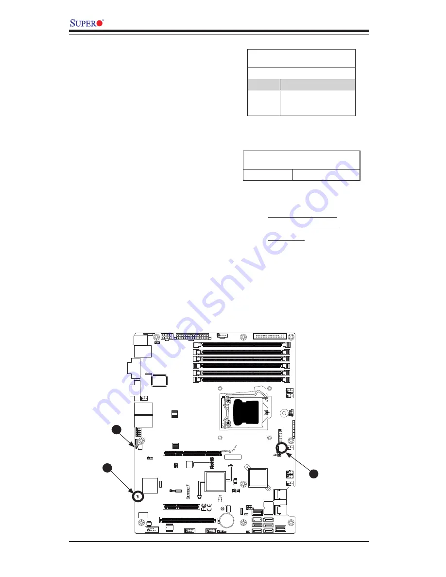
An Onboard Power LED is located at LE4
on the motherboard. When LE4 is on, the
AC power cable is connected. Make sure to
disconnect the power cable before removing
or installing any component. See the layout
below for the LED location.
A. Onboard PWR LED
B. IPMI Heartbeat LED
C. UID LED
IPMI Heartbeat LED (X8SIE-F/X8SI6-F/
X8SIE-LN4F only)
An IPMI Heartbeat LED is located at
LE7. When LE7 blinks, the IPMI functions
properly. Refer to the table on the right for
details. Also see the layout below for the
LED location.
IPMI Heartbeat LED Indicator (LE7)
LED Settings
Green: Blinking
IPMI is ready for use
A
B
C
Rear UID LED
The rear UID LED is located at LE5 on the
backpanel. This LED is used in conjunction
with the front UID LED and the rear UID
switch to provide easy identification of a
system that might be in need of service.
Summary of Contents for X8SI6-F
Page 1: ...USER S MANUAL Revision 1 1b X8SIE F X8SIE X8SIE LN4 X8SI6 F X8SIE LN4F ...
Page 12: ...xii X8SIE X8SIE F X8SI6 F X8SIE LN4 X8SIE LN4F User s Manual Notes ...
Page 28: ...1 16 X8SIE X8SIE F X8SI6 F X8SIE LN4 X8SIE LN4F User s Manual Notes ...
Page 72: ...2 44 X8SIE X8SIE F X8SI6 F X8SIE LN4 X8SIE LN4F User s Manual Notes ...
Page 80: ...3 8 X8SIE X8SIE F X8SI6 F X8SIE LN4 X8SIE LN4F User s Manual Notes ...
Page 104: ...4 24 X8SIE X8SIE F X8SI6 F X8SIE LN4 X8SIE LN4F Notes ...
Page 106: ...A 2 X8SIE X8SIE F X8SI6 F X8SIE LN4 X8SIE LN4F User s Manual Notes ...
Page 111: ...B 4 X8SIE X8SIE F X8SI6 F X8SIE LN4 X8SIE LN4F User s Manual Notes ...


