background image

5

Assembly Instructions

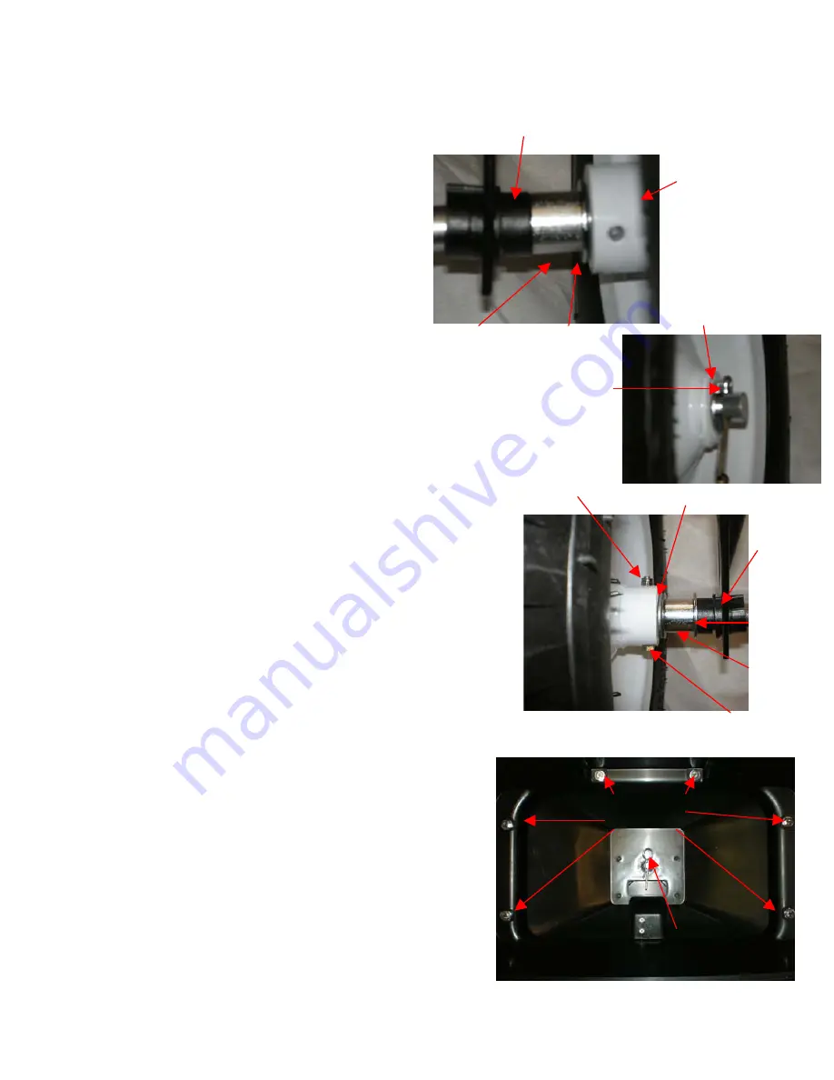
Step# 1: Attaching Tires/Wheel Assembly to 
Axle.

First, on the side of the axle that has the hole drilled 
closest to the tip, put the following parts on in the 
following order:

•Inside Bushing (#18)

•Axle Spacer (#50)

•Big Flat Washer(#16)

•Tire/Wheel Assembly (#14)

•Big Flat Washer (#16)

•Cotter Pin (#15) through the hole in the axle to 
secure parts on axle.

Second, on the other side of the axle put these parts on 
the axle in the following order:

•Inside Bushing (#18)

•Big Flat Washer(#16)

•Axle Spacer (#50)

•Tire/Wheel Assembly(#14)

•2- Big Flat Washers (#16)

•Place Hex bolt M5 x 45 (#27) through rim of tire 
and through the hole in the Axle (#30) and fasten 
with M5 Lock Nut (#28).

See Photo #1

Step #2: Attach Hopper to Frame Tube

Slide Sprocket Shaft (#25) up through the center hole 
in the bottom of the hopper.  Be sure holes in Hopper 
line up with the holes in the Frame Tube.  Place Hair 
Pin (#22) through the hole in the top of the sprocket 
shaft.
Next, secure the hopper to the frame tube using 6 M6 x 
40 Hex Bolts (#3), 6 washers (#2), and  then 6 M6 
Lock Nuts (#9) on the bottom.

SEE Photo #2

Inside Bushing

Axle 
Spacer

Big Flat 
Washer

Tire/Wheel 
Assembly

Big Flat 
Washer

Cotter Pin

Inside 
Bushing

Big Flat 
Washer
Axle 
Spacer

2 Big Flat Washers

M5 Lock 
Nut

M5 x 45 Hex Bolt

Photo #1

Hair Pin

M6 x40 Hex 
Bolts

Photo #2

Summary of Contents for 13696

Page 1: ...Tow Behind Spreader 125 lb Capacity IMPORTANT Read and follow all Safety Precautions and Instructions Before Operating this Equipment Owners Manual 13696 13828 Rev 07 149...

Page 2: ...s from the package of the material you are applying with this unit 7 This unit is not designed to spread sand or gravel These abrasive materials can cause premature failure of the unit Operation Instr...

Page 3: ...sembly Frame 1 D Wheel 2 B Hitch Tongue Ass y 1 E Hopper Ass y 1 C Hitch Brace 2 NOTE If you have questions problems or missing parts please call our customer service before returning to your retailer...

Page 4: ...QTY F Hex Bolt M6 40 7 M Big Washer 6 7 G Hex Bolt M6 35 3 N Flat Washer 8 1 H Inside Hex Bolt M5 45 1 O Flat Washer 16 5 I Cotter Pin 5 35 1 P Wheel Axle Sleeve 2 J Lock Nut M8 1 Q Inside Bushing 2 K...

Page 5: ...ers 16 Place Hex bolt M5 x 45 27 through rim of tire and through the hole in the Axle 30 and fasten with M5 Lock Nut 28 See Photo 1 Step 2 Attach Hopper to Frame Tube Slide Sprocket Shaft 25 up throug...

Page 6: ...it with 2 Washers and an M8 Lock Nut STEP 4 Connecting the Hitch Braces to the Hitch Tube and Frame Tube Connect both hitch tube assembly using 1 M6 x 35 hex bolt 17 and 1 M6 lock nut on each side Ne...

Page 7: ...7 53...

Page 8: ...ock Nut M8 12221 2 39 Rod Pin 12 65 13644 1 13 Spreader Disc 13792 1 40 Hitch Bracket 13810 1 14 Wheel 13793 2 41 Flow Control Plate 13811 1 15 Cotter Pin 5 35 12457 1 42 Sleeve 13812 1 16 Flat Washer...

Page 9: ...BLE PRODUCT ________________ SERIAL NUMBER _______________ MODEL NUMBER _______________ TYPE _______________ PART NUMBER WITH PAINT CODE PART DESCRIPTION TELEPHONE 1 651 330 2038 SUPER4CE PRODUCTS PO...

Reviews: