background image

Superabrasive


User


Manual


Original


Language


Lavina®


25G

X


2/2015


20


8.5


REPLACING


THE


CLUTCH


In


case


the


electric


clutch


has


to


be


replaced,


remove


the


engine


(see


previous


chapter)


and


lay


it


on


its


side


with


the


oil


drainage


up


(Fig.


8.5.1)


and


loose


the


front


nut


to


dismount


the


clutch


(Fig.


8.5.2


and


Fig.


8.5.3


).


Reassemble


in


the


same


manner.


Do


not


forget


to


mount


back


the


washer


on


the


shaft


(Fig.


8.5.4).


The


torque


on


the


front


nut


(Fig.


8.5.3)


to


mount


the


pulley


and


clutch


should


be


70


Nm


or


52


ft


lbs(Fig.


8.5.2


and


Fig.


8.5.3).


8.6


DISMOUNTING


TOOL


HOLDER


TO


CHANGING


V

RINGS


AND


FELT

RINGS


To


check


or


replace


the


buffers


and


the


elastic


elements


,


the


tool


holders


have


to


be


dismounted.


You


will


need


deep


metric


socket


13mm


with


outside


diameter


not


more


than


3/4in


to


unscrew


the


four


bolts


(Fig.8.6.1)


and


remove


the


holder


(Fig.8.6.2)


When


the


tool


holder


is


dismounted,


you


can


change


the


sealers


(V

Ring


and


Felt

Ring).


By


loosening


four


Hex


cap


flange


bolts


(Fig.8.6.3)


the


adaptor


comes


loose.


Unscrew


the


six


screws


of


the


cap


(Fig.8.6.4)


holding


the


felt

ring.


Take


out


the


Felt

Ring,


adaptor


and


V

Ring.


Mount


the


V

Ring


with


the


smallest


lip


of


the


V


to


inside


(Fig.8.6.5)


just


push


the


V

Ring


so


the


top


is


on


the


same


level


as


the


pulley


top


(Fig.8.6.6).


Then


take


the


adaptor


and


push


the


V

Ring


down


with


the


adaptor


(Fig.8.6.7).


The


lowest


lip


of


the


V

Ring


should


only


barely


touch


its


gliding


surface;


also


never


push


the


V

Ring


down


with


fingers.


Mount


the


adaptor


and


the


Felt

Ring


on


top


(Fig.8.6.7).


Close


the


sealers


with


the


cap


(Fig.8.6.8)


and


screw


the


bolts.


Always


use


the


original


bolts.


Figure 8.5.1 

Figure 8.5.2 

Figure 8.5.3 

Figure 8.6.1 
8 2 1

Figure 8.6.2 

Figure 8.6.3 

Figure 8.6.4 

Figure 8.6.5 

Figure 8.6.6 

Figure 8.6.7 

Figure 8.6.8 

Figure 8.5.4 

Summary of Contents for LAVINA 25G-X

Page 1: ...Superabrasive User Manual Original Language Lavina 25G X 2 2015 LAVINA 25G X User Manual Tech Support Line 800 987 8403 www superabrasive com info superabrasive us ...

Page 2: ...Superabrasive User Manual Original Language Lavina 25G X 2 2015 2 ...

Page 3: ...parts are not warranted Superabrasive is not liable for defects arising out of use of non OEM parts The Warranty is void if the purchaser has not followed the maintenance plan stipulated by the machine s manual and warranty card The warranty is void if the purchaser repairs said Goods himself or if repairs are conducted by a repair facility that is not approved by Superabrasive Superabrasive s lia...

Page 4: ...PLACE AFTER THE FIRST 8 WORKING HOURS 16 CHECK AND REPLACE EVERY 50 WORKING HOURS 16 CHECK AND REPLACE EVERY 200 WORKING HOURS 17 CHECK AND REPLACE EVERY 400 WORKING HOURS 17 VACUUM 17 WATER LEAKS 17 MECHANICAL PARTS 17 ELECTRICAL SYSTEM 17 8 TROUBLESHOOTING 18 8 1 ENGINE 18 8 2 CHECKING AND CHANGING OIL 18 8 3 SEPARATING THE HEAD FROM THE CARRIAGE 18 8 4 DISMOUNTING MOUNTING THE ENGINE 19 8 5 REP...

Page 5: ...ns involved MACHINE CHARACTERISTICS The Lavina X machine is made of two main component sections LAVINA 25G X MAIN DESIGN The two main components are the carriage and main head The handle on the frame is adjustable in height and allows the operator to work in a correct and safe posture The halogen spotlight Fig 1 2 enables the operator to work in darker areas Existing lighting system does not repla...

Page 6: ...ional purposes Weight needed for transportation purposes production year and serial number needed for maintenance purposes CUSTOMER SERVICE For customer assistance and technical support call your local distributor or call Superabrasive Inc at 1 800 987 8403 or visit us at www superabrasive com where you can download a copy of this manual 2 SAFETY INSTRUCTIONS RECOMMENDED USE The LAVINA 30GX machin...

Page 7: ... Monoxide Poisoning This is the most frequently reported incident associated with propane powered floor care machines and is caused by excessive exhaust emissions The symptoms are headache dizziness and nausea A major cause involves engines with poor preventive maintenance practices usually those with dirty air filters and machines operated in confined areas without adequate ventilation Another ca...

Page 8: ... on independent testing labs such as UL and CGA before giving their approval of the use of some equipment These labs thoroughly test equipment and submit their stamp of approval only after rigorous testing While not being required by all law enforcement agencies the stamp of approval by these agencies further assures the operator that he or she is working with and around safe equipment NOTE In ord...

Page 9: ... in case of emergency The operator must have an adequate technical knowledge and preparation The operator is expected to operate their equipment safely and responsibly They are responsible for the proper handling and storage of propane cylinders identifying potential hazards associated with his job and avoiding these hazards at all times PROPANE CYLINDERS The Propane cylinders are constructed of e...

Page 10: ...A cylinder rattling around in the back of a vehicle and banging into other objects constitutes a hazard Avoid dropping or banging cylinders against sharp objects The propane cylinders are sturdily constructed but a series of hard jolts could cause damage Please note that any cylinder that has been filled is always considered full no matter how little propane gas remains in it This is because even ...

Page 11: ... construction is rated only for the weight of the machine Do not lift any other loads on the machine Use always hoisting equipment rated for 300 kg or 660 lbs STORAGE Always store and transport the LAVINA X machine in a dry place Never transport the LAVINA X machine unprotected it may be damaged if transported unprotected during rain or snow When during the storage of the machine the temperature m...

Page 12: ...change its elasticity You can make the change after dismounting the holder as per the instruction in TROUBLESHOOTING In Lavina 25G X the holder is initially mounted with 6 buffers Mount the tools only after ensuring that there is enough diamond bond material left Be sure that the plates are always clean before mounting WARNING Always Secure the Quickchange pads with the security plate Fig 4 3 lock...

Page 13: ...ll throttle for best results If working wet add water to the floor surface If working dry omit this step and instead switch on the vacuum unit Finally hold the machine firmly and push the start of the Start Stop clutch button 2 OPERATING THE MACHINE Guide the machine in straight lines across the floor and with each new line overlap a little bit of the previously completed surface Work at a constan...

Page 14: ... additional weights depend on the tools it is not always possible to add weights Some tools work too aggressively and the machine can stop The weight can be ordered with item number A 08 00 00 00 TOOL HOLDER KEY The tool holder key Fig 5 3 is used for adjusting mounting and dismounting of the foam plates Always use the key for mounting Item number is A03 00 00 00 FOAM PLATE Diamond tools with Velc...

Page 15: ... They are 3 inch with included Velcro back attachment NATO polishing discs feature a special resin formula designed for both wet and dry applications and a unique design with wide channels allowing for work on a cleaner surface and ensuring a quality polish Available in 3 and 4 in sizes They are with included Velcro attachment V HARR Premium Polishing Pads are designed for mechanically polishing a...

Page 16: ...ine the operator should conduct a visual inspection of the machine Any defect should be solved immediately Pay attention to power cords plugs and vacuum hoses loose bolt or screws Tool holders Buffers and elastic element are consumables and must be visually checked daily and replaced if needed See that flanges or discs are mounted and locked well in place The key lock holders butterflies should be...

Page 17: ...parts elastic element buffers sealers with the slightest damage or consume Return machine to authorized service center for overall checkup of the Engine For Propane safety have the machine serviced by a Certified Technician including emission check CHECK AND REPLACE EVERY 400 WORKING HOURS Besides the checks of 200 working hours replace sealer and V rings like described in chapter TROUBLESHOOTING ...

Page 18: ...tion Call your dealer or the factory for instructions on where to have the service valve replaced Meanwhile to get by you can continue to open the service valve until you do not hear a click and then the engine will run normally If it does not call your customer service Starter barely turns the engine over or the solenoid just clicks The battery is likely low in charge This can be remedied by rech...

Page 19: ...er Remove front Fig 8 4 1 and back belt protection Fig 8 4 2 Loose the motor base plate Fig 8 4 3 release the tension device Fig 8 4 4 and take out the belt Fig 8 4 5 Take off the engine Fig 8 4 6 Reassemble in the same manner Fig 8 4 7 Tension the belt with bolt 4 on fig 8 4 7 or fig 8 4 4 The belt tension can be tested with a Frequency tension Tester Optibelt 3 TT 190 200Hz or manual by pushing ...

Page 20: ...w the four bolts Fig 8 6 1 and remove the holder Fig 8 6 2 When the tool holder is dismounted you can change the sealers V Ring and Felt Ring By loosening four Hex cap flange bolts Fig 8 6 3 the adaptor comes loose Unscrew the six screws of the cap Fig 8 6 4 holding the felt ring Take out the Felt Ring adaptor and V Ring Mount the V Ring with the smallest lip of the V to inside Fig 8 6 5 just push...

Page 21: ...e adaptor Fig 8 7 12 are reliably tighten Mount the holder on the machine using the same socket as mentioned in 8 6 Fig 8 7 10 Fig 8 7 11 The retaining washer fits into the central hole C of adaptor and the four bolts into the thread holes Т Fig 8 7 12 The holder is centered on the outside diameter of the adaptor Ensure the connection of the holder on the forehead of the adaptor and then tight eve...

Page 22: ...ig 8 8 6 and the screw Fig 8 8 5 ATTENTION NEVER OVER TENSION THE CHAIN THE CHAIN WILL BE DAMAGED 8 9 MOUNTING NEW PLANETARY CHAIN The planetary chain is replaced with new one when the step drive of the chain tensioner is finished or there is a break in the integrity of the chain Unscrew the eight bolts Fig 8 8 1 and take out the cover Fig 8 8 2 and pull out the hose of the water sprayer Fig 8 8 3...

Page 23: ...screw the outer nut Fig 8 8 6 The tensioner of the planetary chain should allow chain sagging 3 5mm 1 8 3 16 in controlled in span X Fig 8 8 7 When ready screw the two nuts Fig 8 8 6 and the screw Fig 8 8 5 ATTENTION NEVER OVER TENSION THE CHAIN THE CHAIN WILL BE DAMAGED 8 10 REPLACING THE PLANETARY DRIVING CHAIN WHEEL AND PLANETARY TENSIONER Check and repeat the instruction in 8 9 MONTING NEW PLA...

Page 24: ...thout force Installation with the use of force is NOT permissible at any time as this can damage the high quality low stretch tension cord and other components This damage is often not visible Put the belts in pos 6 as per the scheme and pay attention for their correct position in every pulley Screw up until it stops and loosen on the half moons the nuts on pos 4 allowing the rotation of the tensi...

Page 25: ... Fig 8 11 14 Fig 8 11 15 Insert the screws up to revolution and by alternating until the conical sleeve pull up the belt pulley The conical sleeve must be aligned in height with the belt washer Fig 8 11 16 Dismounting the planetary belt is possible without removing of the Bottom cover assembly Unscrew the eight bolts take the service window cover and the sealing Fig 8 11 17 Fig 8 11 18 Dismount th...

Page 26: ...l need magnetic deep metric socket 10mm with outside diameter not more than 11 16 in to unscrew the six bolts Fig 8 12 3 Fig 8 12 4 Fig 8 12 5 Driven Chain Wheel is composed by two symmetrical halfs Fig 8 12 6 Mount on the reverse order 8 13 REPLACING THE PULLEY UNITS Dismount guard top cover maintenance window chain tensioner driven chain wheel bottom cover and belts as previous described Unscrew...

Page 27: ...to be replaced send the machine back to Superabrasive or a local distributor where a professional disposal complying with the environment laws and directives is guaranteed 10 MANUFACTURER S CONTACTS If you need to contact Superabrasive Inc with technical support questions below is the contact information Address 9411 Jackson Trail Road Hoshton GA 30548 USA Email info superabrasive us Tel 706 658 1...

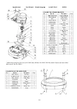
Page 28: ... X TOP COVER 1 PARTS No Item No Description Pcs 1 M6X16DIN6921 Bolt 2 2 L25G 10 00 69 Front Guard 1 3 M8X16DIN6921 Bolt 8 4 L25SPS 07 00 00 02 L Left Fork 1 4 1 L25SPS 07 00 00 02 R Right Fork 1 5 L25X 19 00 00 Top Cover Assembly 1 6 M6X10ISO7380F Screw 5 7 L25NSPS 07 00 00 05 Back Weight Holder 2 8 L25SPS 07 00 00 29 Rubber Buffer 3 9 M10X75DIN931 Bolt 1 10 M10DIN127B Spring Washer 1 11 A29 12 00...

Page 29: ...07 Bolt 4 10 L25G 10 00 66 Tensioning Device Support 1 11 M8X25DIN912 Screw 2 12 M8DIN7980 Spring Washer 2 13 M8X40DIN933 Bolt 1 14 M8DIN125A Washer 6 15 M8DIN127B Spring Washer 9 16 M6X16DIN6921 Bolt 4 17 L25G 10 05 00 Back Guard 1 18 OMEGAHP7608MHP30 Endless Transmission Belt 1 19 M6X30DIN933 Bolt 1 20 M6DIN127B Washer 1 21 M6DIN9021A Washer 2 22 L25G 10 00 67 02 Support 1 23 M8X20DIN6921 Bolt 2...

Page 30: ... Type A 1 16 08B 1 78 Chain 1 17 M6X16DIN6921 Bolt 8 18 А52DIN472 Retaining Ring 1 19 L25X 15 00 12 Chain Pulley 2 20 3205 Roller Assembly 1 21 M8X25DIN7991 Screw 8 22 L25GX 15 20 00 Base plate 1 23 L25GX 15 03 00 Left Plate Assembly 1 24 L25G 10 00 60 Cap for Rotary Seal 1 25 M5X12DIN7991 Screw 4 26 TWVA00700 V Ring Type A 1 27 L25GX 10 30 00 Pulley Unit 1 28 L25SPS 00 00 00 15 Front Washer 1 29 ...

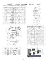
Page 31: ...4 Front Washer 1 9 9 M5X12DIN912 Screw 1 6 LAVINA 25G S WATER TANK PARTS No Item No Description Pcs 1 A29 50 00 Regulator 1 2 1 2 Filter 1 7 LAVINA 25G X BOTTOM COVER 1 PARTS No Item No Description Pcs 1 A41 00 00 Tool Holder A41 3 2 M6X10DIN7991 Screw 36 3 L25LS 14 00 03 Outer Cover 3 4 A42 03 00 Adaptor 3 4 1 М8х16DIN6921 Bolt 4 5 110X90X8 5 Felt Ring 3 6 TWVA00800 V Ring Type A 3 7 L25LS 14 00 ...

Page 32: ... 3 5 A41 21 00 Set of plates 1 4 М8х16DIN6921 Bolt 4 5 A41 20 01 Flange 1 9 LAVINA 25G X BOTTOM COVER 2 PARTS No Item No Description Pcs 1 HP6455MHP15 Timing Belts 1 2 HL24008MHL50 Timing Belts 1 3 M8DIN6923 Nut 13 4 L25L 10 00 14 Sector 1 5 L25L 10 00 12 Sector 1 6 L25L 10 00 07 Support 2 7 L25L 10 00 11 Sector 1 8 L25X 12 00 00 Tensioning Support 1 9 L32C 14 20 04 Nut 1 10 M10DIN934 Nut 2 11 L25...

Page 33: ... A58165 Swivel Bolt 1 22 A29 40 00 Water Flow Control Unit 1 7 L25SPS 01 00 00 00 G Lamp Unit Incl Cable 1 23 M5X12DIN6921 Bolt 4 8 M6X12DIN912 Screw 4 24 A29 20 01 01 Flow Unit Base 1 9 L25S 23 00 02 End Cover 2 25 M20X1 5DIN439B Nut 1 10 L25P 02 00 00 01 Top Bracket 1 26 L25G 22 00 00 Propane Tank Holder 1 11 T34391 Knob Bolt 1 27 M8X16DIN933 Bolt 4 12 M5UN732 Washer 1 28 M8DIN125A Washer 4 13 A...

Page 34: ...1 W3132 Kawasaki FS481V AS10 M 18H 12V 1 K49065 7007 Oil Filter 12 2 W1325 Oil Pressure Switch 6 3 F466230 Elbow 1 4 K59071 7004 Joint 1 5 FE17409029909 Oil Drain Valve 1 6 K11013 7049 Element Air Filter 1 7 K11013 7046 Element Air Filter Fs481v Foam pre Filter 1 8 W3241A Cat Muffler Assy 1 9 W3305 Kawasaki Bonnet Filter 1 ...

Reviews: