background image

Superabrasive 

Owner’s Manual –


LAVINA® 30L Pro /30L HV Pro  

2/2014 

 15


9. TROUBLESHOOTING


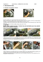
9.1 CHECKING THE TENSION OF THE BELT 


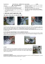
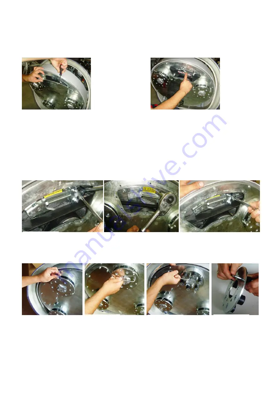
Open the checking cover to reach the belt and tension device (Fig. 9.1.1) 
While tensioning check regularly tension, push the belt down and with a pressure of 71N, this is approximately 7 
kilograms or 15 pounds with this pressure the belt should move 3.5-4 mm or .1/8”  
It is recommended that the tensioning of the belt be measured with Optikrik II Device (Measuring range: 500-1400 N) 
(Fig. 9.1.2) 
The original pressure P=1400 N and after working a while it is P=1100 N. 

ATTENTION: 
NEVER “OVER” TENSION THE BELT, THE BELT WILL BE DISTROYED AND IT WILL NEVER 
RECOVER ITS ORIGINAL TENSION 


Loose the contra nuts (Fig. 9.1.3), loose light the three bolts of the tension device (Fig. 9.1.4), and adjust the tension 
with the nut seen in (Fig. 9.1.5). When the right tension is reached close the contra nut and the three bolt of the support. 
Reassemble in the same manner. Apply sealant to close the cover. 
 

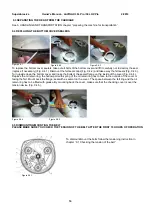
9.2 TOOLHOLDER 


Spider and buffers are consumables and have to be replaced regularly. It is recommended all buffers and spiders to be 
changed. Pull the security springs off the holder (Fig. 9.2.1), dismount the top disc (Fig. 9.2.2), 
Take off the security disc (Fig. 9.2.3), and dismount and mount the buffers with the screw on the backside (Fig. 9.2.4), 
Reassemble in the same manner. 

Figure 9.1.2 

Figure 9.1.1 

Figure 9.2.4 

Figure 9.1.4 

Figure 9.1.5 

Figure 9.2.1 

Figure 9.2.3 

Figure 9.1.3 

Figure 9.2.2 

Summary of Contents for Lavina 25L HV Pro

Page 1: ...1 LAVINA 30L Pro User Manual Tech Support Line 800 987 8403 www superabrasive com info superabrasive us ...

Page 2: ...AND INSPECTION Cleaning 12 Check Daily 12 Check and replace after the first 15 working hours 12 Check Every 200 Working Hours 12 Check Every 500 Working Hours 12 Vacuum 12 Water Leaks 12 Electrical system 12 Mechanical Parts 12 Electrical System 13 Lavina30 L Pro Electrical schemes 208 240 Volt 13 Lavina25 NHV Pro Electrical schemes 380 480 Volt 14 9 TROUBLESHOOTING 9 1 Checking tension of the bel...

Page 3: ...ons only Every other use may possess risks to the persons involved MACHINE CHARACTERISTICS The LAVINA 30L Pro 30L HV Pro is made of two main component sections LAVINA 30L PRO 30L HV PRO MAIN DESIGN The two main component sections the carriage and main head The handle on the frame is adjustable in height and allows the operator to work in a correct and safe posture The halogen spotlight Fig 1 2 ena...

Page 4: ... within the limits of directive 2003 10 EC the seventeenth individual Directive of Article 16 1 of Directive 89 391 EC However as previously stated the operator must wear ear protectors LABEL DATA The data on the label provides the correct voltage and kW needed for operational purposes Weight needed for transportation purposes production year and serial number needed for maintenance purposes CUSTO...

Page 5: ...ng up Risks due to wearing inappropriate working clothes Training Risks due to lack of operational training NOTE In order to reduce all consequences of the above mentioned risks we advise that machine operators will follow the instructions in the manual at all times RESIDUAL RISKS During the normal operating and maintenance cycles the operator is exposed to few residual risks which cannot be elimi...

Page 6: ...ase the pin sets Fig 3 3 which attach the head to the carriage Pull out the vacuum hoses Fig 3 1 and dismount the head from the carriage Fig 3 4 The head of the LAVINA 30L Pro 30L HV Pro has one bar and a support used as handles intended for easy moving and transportation LIFT THE MACHINE FROM WORKING TO TOOL MOUNTING POSITION Push the front handle down and swivel it to the front Fig 3 4 Pull the ...

Page 7: ...ion for changing the tools Mount the tools only after ensuring that there is enough diamond bond material left Be sure that the plates are always clean before mounting Always use the tool holder key Fig 4 1 Diamond tools with Velcro are attached on three foam plates of 13 5 inch The foam plates Fig 4 2 are mounted the same way as the other tools THE CONTROL BOARD FIG 4 3 1 Digital RPM indicator in...

Page 8: ...eck regularly if your vacuum works properly STOPPING THE MACHINE The stopping of the machine must be done gradually until the motor stops Do not stop moving the machine before arresting the motor as the tools could damage the surface To stop push the off button 8 Use the Emergency button 9 only in emergency or use it to switch the power totally off Remember not to hold the machine in one spot befo...

Page 9: ...used wet or dry and are best for hard concrete applications NATO polishing discs feature a special resin formula designed for both wet and dry applications and a unique design with wide channels allowing for work on a cleaner surface and ensuring a quality polish Available in 3 and 4 in sizes V HARR Premium Polishing Pads are designed for mechanically polishing and restoring concrete also ideal fo...

Page 10: ...riage Fig 7 2 Exploded view of the main head top cover motor belt and weight support Fig 7 3 Exploded view of the main head base plate and pulleys Fig 7 4 Exploded view of the main head bottom cover Fig 7 5 Exploded view of the tool holder Fig 7 6 Exploded view of the SAM tool holder Fig 7 7 Figure 7 2 Figure 7 4 Figure 7 11 Figure 7 3 ...

Page 11: ...Superabrasive Owner s Manual LAVINA 30L Pro 30L HV Pro 2 2014 11 Figure 7 5 Figure 7 6 Figure 7 7 ...

Page 12: ...ly inspect and clean the tool plate connections power cord and plugs vacuum hoses and water tank Also check the water flow Check the guard assembly Make certain the wheels are clean and rotate properly Inspect the control buttons If there are defective control parts they should be replaced immediately Replace worn vacuum and water hoses Carefully inspect the seal rings and bearings of the grinding...

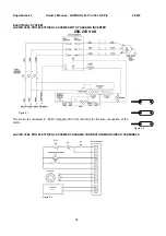
Page 13: ...STEM LAVINA 30 L PRO ELECTRICAL SCHEMES WITH YASKAWA INVERTER 208 240 Volt The motor is connected in Delta triangle 230 Volt reminder for the wire connection of the motor LAVINA 30 L PRO ELECTRICAL SCHEMES YASKAWA CONNECTION MAIN CIRCUIT TERMINALS Figure 8 3 Figure 8 2 Figure 8 1 ...

Page 14: ...AVINA 30 LHV PRO ELECTRICAL SCHEMES WITH YASKAWA INVERTER 380 480 Volt The motor is connected in Star 380 Volt reminder for the wire connection of the motor LAVINA 30 LHV PRO ELECTRICAL SCHEMES YASKAWA CONNECTION MAIN CIRCUIT TERMINALS Figure 8 4 Figure 8 5 Figure 8 6 ...

Page 15: ...STROYED AND IT WILL NEVER RECOVER ITS ORIGINAL TENSION Loose the contra nuts Fig 9 1 3 loose light the three bolts of the tension device Fig 9 1 4 and adjust the tension with the nut seen in Fig 9 1 5 When the right tension is reached close the contra nut and the three bolt of the support Reassemble in the same manner Apply sealant to close the cover 9 2 TOOLHOLDER Spider and buffers are consumabl...

Page 16: ...lange on the inside of the cover Fig 9 4 4 Replace the oil retain ring the hollow part with spring of the oil retain ring has to face to the outside of the cover or facing the felt Mount back the flange seal with a sealant on the cover The space between the felt ring and the oil retain ring has to be filled with grease By mounting back the cover make sure that the checking cover is over the tensio...

Page 17: ...sc Fig 9 6 2 An oil seal ring Fig 9 6 3 and a seal Fig 9 6 4 should be placed on top of the pulley before mounting 9 7 MOTOR CONNECTION In case of changing the motor please check the cable connection to your motor Lavina30 L PRO The motor is connected in Delta Triangle 230 Volt reminder for the wire connection of the motor Lavina 30 LHV Pro The motor is connected in Star 380 Volt reminder for the ...

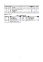
Page 18: ...uperabrasive Owner s Manual LAVINA 30L Pro 30L HV Pro 2 2014 18 9 8 FAULT DIAGNOSIS INVERTER YASKAWA V1000 Pages are referring to Yaskawa Electric SIEP C710606 18A YASKAWA AC Drive V1000 Technical Manual ...

Page 19: ...Superabrasive Owner s Manual LAVINA 30L Pro 30L HV Pro 2 2014 19 ...

Page 20: ...Superabrasive Owner s Manual LAVINA 30L Pro 30L HV Pro 2 2014 20 ...

Page 21: ...rranty is limited to repair or replacement of covered components and reasonable labor expenses All warranty returns must be shipped freight prepaid The above warranty conditions may be changed only by Superabrasive Superabrasive reserves the right to inspect and make a final decision on any machine returned under this warranty This warranty applies to new used and demo machines Superabrasive does ...

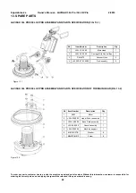
Page 22: ... customer is responsible for ordering the correct part and no shipping charges will be refunded if the part ordered is wrong Item Number Description Qty 1 L30L 10 00 00 Main Head 1 2 L25L 20 00 00 Carriage With Control Box 1 3 D40L670 Vacuum Hose 2 4 L25SPS 07 03 00 00 Pin Assembly 2 Item Number Description Qty 1 S253 Motor 1 2 L25L 04 00 00 Upper Cover assembly 1 3 L25L 15 00 00 Base Plate assemb...

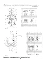
Page 23: ...the correct part and no shipping charges will be refunded if the part ordered is wrong Item Number Description Qty 1 L25L 14 00 00 Bottom Cover Assembly 1 2 M5x16DIN933 Bolt 12 3 M5DIN433 Washer 12 4 OR6x2 O Ring 3 5 M6x12DIN7991 Screw 18 6 L25L 14 00 02 Flange 3 7 TREB01000N7MM Seal 3 8 L25L 10 00 24 Ring 3 9 L25 L 10 00 10 Outer Cover 3 10 М6х10DIN7991 Screw 18 11 A25 00 00 10 Tool Holder 3 12 L...

Page 24: ... 00 01 Top Cover 1 2 L25SPS 04 01 00 00 Vacum Port 2 3 M5x16DIN84A Screw 4 4 M5DIN125A Washer 4 5 M5DIN127B Washer 4 6 M5DIN934 Nut 4 Item Number Description Qty 1 L25L 13 00 00 Deflection Pulley 1 2 M8DIN127B Washer 11 3 M8DIN934 Nut 11 4 L25L 10 00 15 Support 1 5 L25L 12 00 00 Tension Support 1 6 L25L 10 00 16 Support 1 7 M6DIN7980 Washer 1 8 M6x30DIN933 Bolt 1 9 DIN6885A12X8X36 Key 1 10 PL2476 ...

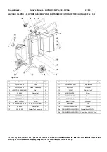
Page 25: ... Bar 1 14 L25SPS 07 00 00 26 Pin 1 15 L25SPS 07 00 00 25 Spring 1 16 М8х25DIN7991 Screw 2 17 М8х20DIN912 Screw 6 18 М8DIN127В Washer 6 19 L25SPS 07 00 00 02 R Right fork 1 To order any parts customer has to provide the machine model and serial number Without this information customer is responsible for ordering the correct part and no shipping charges will be refunded if the part ordered is wrong ...

Page 26: ...lt 1 10 A26 00 00 Water Tank Assembly 1 Item Number Description Qty 11 L25P 02 00 00 01 Top Bracket 1 12 M5UN732 Washer 1 13 T34391 Swivel Bolt 1 14 M8x12DIN7991 Screw 4 15 M8x25DIN912 Screw 4 16 M8DIN125 A Washer 4 17 M8 DIN127 B Washer 4 18 М8DIN934 Nut 4 19 L25SPS 02 00 01 00 Guard 1 20a CB 15HP 3PH 240V PRO Control box L30L Pro 1 20b CB 15HP 3PH 480V PRO Control box L30LHV Pro 1 To order any p...

Page 27: ...350 1635 0 HO7BQ F4x6 Plug With Cable 1 Fig 13 9 L30 L PRO 11 NВ1 63 1P 4A Automatic Breaker 1 Fig 13 9 L30 L PRO 12 230 12 24V 50 46 4VA Transformer 1 Fig 13 9 L30 L PRO 13 SZ1RV1202 Potentiometer 1 Fig 13 9 L30 L PRO 14 NP2 BA21 Button 1 Fig 13 9 L30 L PRO 15 ZBPO Cap 3 Fig 13 9 L30 L PRO 16 NP2 BA42 Button 1 Fig 13 9 L30 L PRO 17 NP2 BA31 Button 1 Fig 13 9 L30 L PRO 18 XB7 ES542 P Emergency Sto...

Page 28: ...th Cable 1 Fig 13 10 L30 LHV Pro 11 NВ1 63 1P 4A Automatic Breaker 1 Fig 13 10 L30 LHV Pro 12 460 12 24V 50 46 4VA Transformer 1 Fig 13 10 L30 LHV Pro 13 SZ1RV1202 Potentiometer 1 Fig 13 10 L30 LHV Pro 14 NP2 BA21 Button 1 Fig 13 10 L30 LHV Pro 15 ZBPO Cap 3 Fig 13 10 L30 LHV Pro 16 NP2 BA42 Button 1 Fig 13 10 L30 LHV Pro 17 NP2 BA31 Button 1 Fig 13 10 L30 LHV Pro 18 XB7 ES542 P Emergency Stop 1 F...

Page 29: ... surface profile It is NOT possible to remove some buffers in order to get more flexibility The buffers and the spider are consumables and have to be checked constantly In case the buffers break the springs will hold the tool on the flange although it is impossible to use the machine and the all the buffer should be replaced A tool can be attached with use of the tool holder key To order any parts...

Reviews: