background image

Superabrasive 

Owner’s Manual Original Language – Lavina 

® 

3213E/3213EHV 

2/2020 


23


(Fig.8.4.2) is 

INADMISSIBLE

 because the security system preventing the separation of part of the holder in case of 

broken buffers and elastic element will not function!  You can  change the butterfly of the holder without  dismounting 
the holder of the machine. 


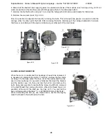
Fig.8.4.13  is  3-d  section  view  of  the 
holder, 

showing 

its 

parts. 

The 

numbering  is  the  same  as  in  Spare 
parts. 


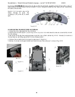
8.5 SEPARATING THE HEAD FROM THE CARRAGE 

1. Unplug the motor cable plug from the control box  
2. Unscrew the two bolts about 1-1.5 turn /Fig. 8.3.2-2; Fig. 8.3.2-3;/.to disconnect the vacuum connector/Fig. 8.3.2-4/ 
from the carriage. 
3. Disconnect the flexible hose supplying water under the cover of the machine/Fig.  8.3.3-1/. All water connections in 
the machines are with fittings types

„Push-In “and „Release button”. 


4. Unscrew the two bolts /pos.2/ to remove the panel /pos.1 / /Fig.8.3.4/. 
5. Remove the lamps /on magnetic attachment/ and disconnect the cable /pos.1 and pos.2 Fig. 8.3.5/. 

Figure 8.3.4 

Figure 8.4.13 

Figure 8.3.3 

Figure 8.3.1 

Figure 8.3.2 

Summary of Contents for LAVINA ELITE 3213EHV

Page 1: ...LAVINA ELITE L3213E User Manual Tech Support Line 800 987 8403 www superabrasive com info superabrasive us ...

Page 2: ...Superabrasive Owner s Manual Original Language Lavina 3213E 3213EHV 2 2020 2 ...

Page 3: ...r parts are not warranted Superabrasive is not liable for defects arising out of use of non OEM parts The Warranty is void if the purchaser has not followed the maintenance plan stipulated by the machine s manual and warranty card The warranty is void if the purchaser repairs said Goods himself or if repairs are conducted by a repair facility that is not approved by Superabrasive Superabrasive s l...

Page 4: ...H YASKAWA INVERTER 380 480 VOLT 19 8 TROUBLESHOOTING 21 INDEX OF PROBLEMS AND SOLUTIONS 21 8 1 REPLACING POWER CORD AND PLUGS 21 8 2 MOTOR CONNECTION 21 8 3 DISMOUTING TOOL HOLDERS TO CHANGING V RINGS AND FELT RINGS 21 8 4 DISASSEMBLING AND MOUNTING TOOL HOLDERS TO CHANGING BUFFERS AND ELASTIC ELEMENT 22 8 5 SEPARATING THE HEAD FROM THE CARRAGE 23 8 6 REPLACING THE MOTOR 24 8 7 FAULT DIAGNOSIS INV...

Page 5: ... The Lavina 32E 32EHV is made of two main component sections LAVINA 32E 32EHV MAIN DESIGN The two main component sections are the carriage and main head The handle on the frame is adjustable in height and enables the operator to work in a correct and safe posture The controls are positioned on top of the handle fig 1 1 Two LED lights Fig 1 2 enable the operator to work in darker areas The lamps ar...

Page 6: ...and kW needed for operational purposes Weight needed for transportation purposes production year and serial number needed for maintenance purposes CUSTOMER SERVICE For customer assistance and technical support call your local distributor or call Superabrasive Inc at 1 800 987 8403 or visit us at www superabrasive com where you can download a copy of this manual LAVINA 3213E LAVINA 3213EHV Voltage ...

Page 7: ... Entanglement Risks due to wearing inappropriate working clothes Training Risks due to lack of operational training NOTE In order to reduce all consequences of the above mentioned risks we advise that machine operators will follow the instructions in the manual at all times RESIDUAL RISKS During the normal operating and maintenance cycles the operator is exposed to few residual risks which cannot ...

Page 8: ... turn the steering bracket Fig 3 1 3 to a new position To turn the steering bracket down Fig 3 3 you have to loosen the swivel bolt Fig 3 1 2 and push it in for security reasons To change the handle positions pull the knob Fig 3 1 1 Fig 3 4 and move the handle up or down By loosening the swivel bolt Fig 3 1 2 one can turn the steering bracket Fig 3 1 3 to a new position To turn the steering bracke...

Page 9: ...stay in four different positions Fig 3 6 Put the weights in pos 1 when the machine is in position to change the working tools The weights are locked in pos 2 pos 3 and pos 4 Fig 3 7 The pressure on the working tools is different in each of the four weights positions See the Technical Data Figure 3 6 4 Figure 3 6 2 Figure 3 6 3 Figure 3 6 1 Figure 3 7 ...

Page 10: ...urn Fig 3 9 2 Fig 3 9 3 to disconnect the vacuum connector Fig 3 9 4 from the carriage 2 Put the machine in position to change the tools Fig 3 5 3 Unscrew the bolt holding the guard Fig 3 10 1 and the two bolts on the back stoppers Fig 3 10 2 4 You can dismount the guard as shown on Fig 3 10 3 and Fig 3 10 4 3 6 THIRD WHEEL Lavina 32E has a third wheel for easier handling It has two positions fig ...

Page 11: ...e of the tank Fig 3 12 Using compressed air blow out excess water from the system at each position of the tap water ball valve Fig 3 12 4 OPERATION 4 1 PRELIMINARY CONTROLS Inspect the working area as explained in the safety instructions For wet use fill the water tank with the electrical cable disconnected Connect the vacuum extractor and ensure that the vacuum hose is clear and able to follow th...

Page 12: ...ially mounted with 6 buffers Mount the tools only after ensuring that there is enough diamond bond material left Be sure that the plates are always clean before mounting WARNING Always Secure the Quick Change tools with the security plate Fig 4 6 lock with the tool holder key Fig 4 6 and make sure that the butterfly is securely locked at 90 degrees Always use the tool holder key Fig 5 3 4 4 VACUUM...

Page 13: ...le it will redirect your browser to Lavina manuals page 9 READY ON OFF switch The switch returns to its starting position after being released If you want to start the motor it must be ON as it puts the inventor into standby mode it glows when it s turned ON If it s off the inventor will be out of standby mode and you cannot start the motor 10 Cup holder 11 Potentiometer controls the RPM of the gr...

Page 14: ...ce When working wet select the destination of the water feed with the water tap fig 4 2 1 and periodically run the pump fig 4 9 5 to release water onto the floor surface Starting the pump is possible only if the machine motor is on When working dry check the floor surface periodically for dust accumulation Check regularly to see if your vacuum works properly 4 8 STOPPING THE MACHINE The stopping o...

Page 15: ... or dry and are best for hard concrete applications They are 3 inch with included Velcro back attachment NATO polishing discs feature a special resin formula designed for both wet and dry applications and a unique design with wide channels allowing for work on a cleaner surface and ensuring a quality polish Available in 3 and 4 in sizes They are with Velcro attachment V HARR Premium Polishing Pads...

Page 16: ...ool plate connections power cord plugs vacuum hoses and water tank filter Also check the water flow of the pump Check the guard assembly Ensure the wheels are clean and rotate properly Inspect the control buttons If there are defective control parts they should be replaced immediately Replace any worn vacuum or water hoses Open the service cover on the motor base to check the planetary chain Lubri...

Page 17: ...r s Manual Original Language Lavina 3213E 3213EHV 2 2020 17 LAVINA 32E ELECTRICAL SCHEMES WITH YASKAWA INVERTER 200 240 VOLT The motor is connected in Delta triangle 230 Volt reminder for the wire connection of the motor ...

Page 18: ...Superabrasive Owner s Manual Original Language Lavina 3213E 3213EHV 2 2020 18 ...

Page 19: ...Owner s Manual Original Language Lavina 3213E 3213EHV 2 2020 19 LAVINA 32EHV ELECTRICAL SCHEMES WITH YASKAWA INVERTER 380 480 VOLT The motor is connected in Star 380 Volt reminder for the wire connection of the motor ...

Page 20: ...Superabrasive Owner s Manual Original Language Lavina 3213E 3213EHV 2 2020 20 ...

Page 21: ...nnection of the motor Lavina 32EHV The motor is connected in Star 380 Volt reminder for the wire connection of the motor 8 3 DISMOUTING TOOL HOLDERS TO CHANGING V RINGS AND FELT RINGS To check or replace the buffers and the elastic elements the tool holders have to be dismounted You will need a 13mm deep metric socket with an outside diameter of no more than 3 4in to unscrew the four bolts Fig 8 3...

Page 22: ...ement Replace the retaining washer Fig 8 4 8 and push the locking pin Fig 8 4 9 This will prevent the washer from falling while mounting the holder on the machine Make sure the four bolts holding the adaptor Fig 8 4 12 are reliably tightened Mount the holder on the machine using the same socket as in 8 3 Fig 8 4 10 Fig 8 4 11 The retaining washer fits into the central hole C of adaptor and the fou...

Page 23: ...e parts 8 5 SEPARATING THE HEAD FROM THE CARRAGE 1 Unplug the motor cable plug from the control box 2 Unscrew the two bolts about 1 1 5 turn Fig 8 3 2 2 Fig 8 3 2 3 to disconnect the vacuum connector Fig 8 3 2 4 from the carriage 3 Disconnect the flexible hose supplying water under the cover of the machine Fig 8 3 3 1 All water connections in the machines are with fittings types Push In and Releas...

Page 24: ...collision with the engine oil drain plug or other part of the main head 8 6 REPLACING THE MOTOR When the motor or central shaft or bearings of need to be replaced it is necessary to dismount the motor To do this unscrew the four bolts 3 fixing it to the base plate The hole 3 at the central shaft can be used to clean surfaces if movement is hindered Dismount the holders and the bottom cover 5 then ...

Page 25: ...asive Owner s Manual Original Language Lavina 3213E 3213EHV 2 2020 25 8 7 FAULT DIAGNOSIS INVERTER YASKAWA V1000 Pages are referring to Yaskawa Electric SIEP C710606 18A YASKAWA AC Drive V1000 Technical Manual ...

Page 26: ...Superabrasive Owner s Manual Original Language Lavina 3213E 3213EHV 2 2020 26 ...

Page 27: ...en the outer nut Fig 8 8 7 The tensioner of the planetary chain should allow chain sagging of 3 5mm 1 8 3 16 in measured in span X Fig 8 8 7 When the tension is set screw the two nuts Fig 8 8 6 Fig 8 8 7 and the two bolts Fig 8 8 4 Fig 8 8 5 ATTENTION NEVER OVER TENSION THE CHAIN THE CHAIN WILL BE DAMAGED 8 9 MOUNTING NEW PLANETARY CHAIN The planetary chain is replaced with new one when the step d...

Page 28: ...in and the split pin Fig 8 9 8 Fig 8 9 9 To tension the chain screw the outer nut Fig 8 9 4 The tensioner of the planetary chain should allow chain sag of 3 5mm 1 8 3 16 in measured in span X Fig 8 8 7 With tension set screw the two nuts Fig 8 9 3 1 Fig 8 8 8 and the two bolts Fig 8 9 3 Fig 8 9 4 ATTENTION NEVER OVER TENSION THE CHAIN THE CHAIN WILL BE DAMAGED 8 10 REPLAING THE FRONT KEY JOINT OF ...

Page 29: ... bearings of pulley units and tensioners are in good condition check for too much clearance or rolling noise Rotating the tensioner will allow the centre distance to be reduced so the timing belt may be fitted without force Put the belts in pos 11 as per the scheme and pay attention to their correct orientation at each pulley Ensure that you have loosened the nuts at pos 8 and the six bolts at pos...

Page 30: ...he safety cap Fig 8 13 1 3 of the new gear and mount to the shaft Fold the safety washer as shown on Fig 8 13 1 and screw the bolt using the blue thread locking adhesive Tightening force on the bolts should be 22 25 N m 16 18 lbf ft Screw the safety washer as shown on Fig 8 13 1 When mounting the new gear put silicone sealant in pos 4 of Figure 8 13 1 The central gear consists of two halves which ...

Page 31: ...r a local distributor where a professional disposal complying with the environment laws and directives is guaranteed 10 MANUFACTURER S CONTACTS If you need to contact Superabrasive Inc with technical support questions below is the contact information Address 9411 Jackson Trail Road Hoschton GA 30548 USA Email info superabrasive us Tel 706 658 1122 Fax 706 658 0357 Website www superabrasive com ...

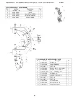
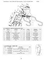
Page 32: ...Assembly 1 6 L32RE04 00 00 Third wheel L32E 1 7 L32E03 00 00 Misting nozzle left support 1 8 L32E01 00 00 1 Front Frame L32E 1 1 11 2 LAVINA 3213E MISTING NOZZLE SUPPORT L32E No Item No Description Pcs 1 30301210051 BoltM6X16DIN6921 3 2 30313000344 Adapter 1 4 INC NPT1 4 1 3 30313000064 Misting nozzle 1 4 L20GX 01 10 02 Insert for Misting nozzle 1 5 30301240015 Nut M20x1 5DIN439 B 1 11 3 LAVINA 32...

Page 33: ...VINA3213E FRONT FRAME PARTS No Item No Description Pcs 1 30301210021 BoltM10x35 4 2 30301240084 NutM10DIN6923 4 3 See table 11 9 PE Tube 1 4 30313000343 EQUAL TEE 1 4 INC 1 4 INC 2 5 30313000344 Adapter 1 4 INC NPT1 4 2 6 L20GX 01 10 02 Insert for Misting nozzle 2 7 30313000064 Misting nozzle 2 8 30301240015 Nut M20x1 5DIN439 B 2 9 See table 11 9 PE Tube 1 10 See table 11 9 PE Tube 1 11 3030124009...

Page 34: ...Superabrasive Owner s Manual Original Language Lavina 3213E 3213EHV 2 2020 34 ...

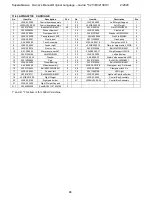
Page 35: ...ght 1 30 L32GE20 00 12 Plate for weight axis L32GE 2 9 L32E20 00 14 Front cover 1 31 30301210058 Bolt M8X12DIN6921 10 10 А57 00 00 00 Water pump set A57 1 32 L32RE20 00 11 Weight support L32RE 2 11 30301240106 Nut M8DIN985 6 33 L32E20 02 00 Left pad holder 1 12 L32D 10 00 24 Washer 2 34 А58 00 00 00 Water Valve assembly L32E 1 13 30310000005 Pad 4 35 30301210033 Bolt M10X20DIN6921 6 14 L32Е29 00 0...

Page 36: ...Support handle L32E 1 6 30301210021 Bolt M10X35DIN 6921 4 17 30301240092 Nut M10DIN985 4 7 30301230035 Screw M6X25DIN912 8 18 L32RE21 00 00 K Frame 1 8 30301220013 Spring Washer M6DIN7980 8 19 30301210096 Bolt M10X35DIN 6921 6 9 L32E23 10 00 Handle support 1 20 30301240106 Nut M8DIN985 4 10 L32E20 00 13 Handle support plate 1 21 L32E20 00 08 Tank support 2 11 L32C 23 00 06 Screw 2 22 30301230027 S...

Page 37: ... 2 30301230098 Screw M6x16DIN 912 1 3 30301210110 Bolt M5x16DIN6921 1 4 30313000348 Fixed Elbow NPT Thread 3 5 30301240103 Nut М6DIN985 1 6 30313000057 UNIJET Body 1 7 30313000058 TEEJET Cup Strainer 1 8 A47 00 00 01 Orifice Plate 1 9 30313000060 UNIJET ADAPTER 1 10 30313000339 Tube To Hose Stem 1 11 11 LAVINA 3213E WATER PUMP PARTS No Item No Description Pcs 1 30326000002 Pump 113C M8234 1 2 3031...

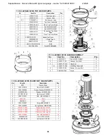
Page 38: ... Item No Description Pcs 1 30301210117 Bolt M6X20DIN6921 2 2 L32E10 71 00 Vacuum Port L32E 1 3 L32E10 70 01 K Guard set 1 3 1 L32Е10 73 00 K Limitary tape set 3 4 L32Е10 72 00 Bottom Vacuum Port 1 5 FBL1350 2780 Brush 1 11 14 LAVINA 3213E PLANETARY CHAIN PARTS No Item No Description Pcs 1 S321 Electro Motor 1 2 30301210019 Bolt M16X35DIN933 4 3 30301220006 Spring Washer M16DIN127B 4 4 M16DIN125A W...

Page 39: ...6921 24 6 L3213E10 08 00 Bottom Cover Assembly 1 6 1 L3213E10 08 01 Bottom Cover 1 6 2 30301230017 Screw M6X10DIN7991 10 9 36 6 3 L25LS 14 00 02 Flange 3 6 4 L25LS 14 00 03 Outer Cover 3 7 D4X2X2500 Seal 1 11 17 LAVINA 3213E TOOL HOLDER PARTS SEE ALSO FIG 8 4 13 No Item No Description Pcs 1 A64 10 00 Quick Change Assembly 1 1 1 A63 12 00 Keylock Set 1 1 2 A41 11 00 Quick Change plate 1 1 3 A41 12 ...

Page 40: ...00 00 Pulley Unit 2 8 L25L 10 00 08 Washer 2 18 L38G 10 00 05 Sector 1 1 9 L3213E13 00 00 Driving Pulley Unit 1 19 L38G 10 00 06 Sector 2 1 10 L3213E15 00 00 Deflection Pulley 1 20 30301210092 Bolt М8х40DIN6921 3 21 30301260069 Key12x8x56 1 11 19 LAVINA 3213E CENTRAL SHAFT BEARNING PARTS No Item No Description Pcs 1 30301230002 Screw M6X16DIN7991 6 2 L32D 11 00 03 Cap 1 3 30303000012 Roller Assemb...

Page 41: ...7 Retaining Ring A52DIN472 1 8 L38GRX 13 00 06 R1 K Shaft Assembly 1 9 30301230141 Screw М5X8DIN914 3 10 30301260051 Key6X6X36 1 11 30302000108 O Ring 21x2 1 11 21 LAVINA 3213E PLANETARY TENSIONING UNIT No Item No Description Pcs 1 L3213E17 20 00 Tensioning Support 1 1 1 L3213E17 21 00 K Tensioning chain sprocket 1 2 30301240099 Nut M10DIN 934 2 3 30301221005 Washer M10DIN125A 1 11 22 LAVINA 32E M...

Page 42: ...1000750 Cap 3 3 30311000717 EMG Button 1 16 L32E24 22 00 Cable X2 1 4 30311000740 Power glowing button 1 17 L32E24 21 00 Cable X1 1 5 30311000721 Switch 2 18 L25E22 00 02 Box 1 6 30311000731 K Switch 1 19 L25E22 00 01 Seal 1 7 30311000732 K Switch 1 20 30301230264 Screw M6x20ISO7380F 10 9 6 8 30311000690 Potentiometer 1 21 30301221003 Washer M6DIN125A 6 9 30350000045 Cup holder 1 22 30301240103 Nu...

Reviews: