Instructional Sheet
SWDCK-RGB-240
Important: Read all instructions prior to installation.
Color Chasing RGB LED Flexible Light Strip Kit
Remote Pairing
The controller and remote is 1 to 1 paired as default. The controller
can only be controlled by a paired remote. When an extra remote is
needed or the controller needs to be matched to any remote, the user
can match the remote by following the instructions below.
Pairing a New Remote
Unplug the controller power and plug in again after 10 seconds.
Press the ‘MODE-’ and ‘LENGTH-’ keys at same time once within 5
seconds after the power is on, then release the keys and press the
‘MODE+’ key once within another 5 seconds. The controller can be
paired to maximum 5 remotes.
Pairing a Any Remote
Unplug the controller power and plug in again after 10 seconds.
Press the ‘MODE-’ and ‘LENGTH-’ keys at same time once within
5 seconds after power is on, then release the keys and press the
‘DEMO’ key once within another 5 seconds.
Pairing to One Remote
Unplug controller power and plug in again after 10 seconds. Press
the ‘MODE-’ and ‘LENGTH-’ keys at the same time once within 5
seconds after power is on, then release the keys and press ‘SPEED-’
key once within another 5 seconds.
1 - Color Chasing RGB LED Light Strip
(SWDC-RGB-240)
1 - Color Chasing RGB Controller w/ RF Remote
(MCB-RGB-DC99)
1 - 12VDC 60W Desktop Power Supply
(
GST60A12-P1J YP12+YC12
)
10 - Mounting Clips w/ Two Screws Each
(SWDC-MC-K)
Parts Included
Remote Functions
Part Number:
Installation Instructions
Pre-test LED Confi gure
Remove strip from the reel and make connections to the controller
and power supply (see “Method 1” diagram). Briefl y turn on the strip
using the included remote control to ensure proper operation of the
strip, controller, power supply, and remote.
See Method 1 diagram for a guide to installing and connecting LED
strip to included controller and power supply for your application.
Choose your desired yet suitable location for the power supply and
controller. Controller can be hidden for use with RF remote control.
Use mounting clips to secure the LED strip to a surface.
Power Supply
The power supply jack is a 5.5mm diameter DC socket.
The main
unit can work at DC 5V to 24V. Since the power supply is directly
connected to the LED signal output, please make sure the power
voltage is same as the LED strip, otherwise the incorrect voltage
may damage LED strip. In this case you will want a 12 VDC power
suopply for the strip and controller.
Output Signal
The output signal is in a SM type plug. The cable at the ` ` maker
side is power supply, the cable sequence is power-data-clock-ground.
The control signals are running at high speed, LEDs may not work
properly if the data cable is too long or gets interfered with. In this
case, shorten the data cable from controller to LED or install the
controller close to the LED strip.
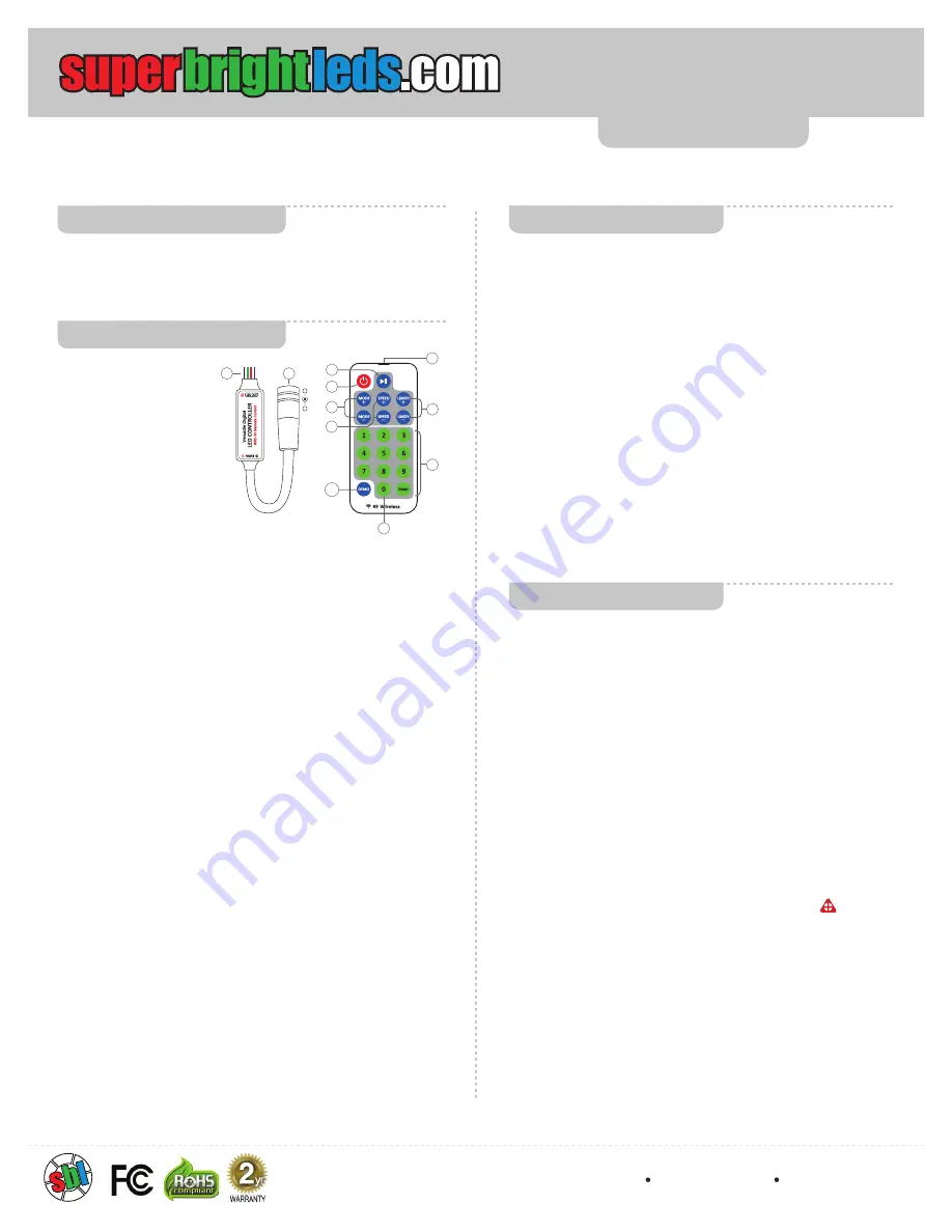
1. Power Input
The power supply input.
The DC jack’s inner pin is
positive and outer sleeve is
negative.
2. Signal Output
Black / Ground,
Green / Clock, Red / Data,
Blue / 12V+
3. Mode Adjust
Adjusts running mode.
Jump to the next mode by
pressing ‘MODE+’ or jump to the previous mode by pressing ‘MODE-’.
4. Speed (Brightness) Adjust
Adjusts the running speed of a dynamic mode or the brightness of a
static color. There are 10 diff erent levels for both speed and brightness.
5. Pause / Play
Toggles between Play and Pause modes. The button will also quit pause
mode and start to play if the running mode is changed.
6. Turn On / Standby
Turns on or switches to standby mode. The main unit will memorize the
current setting. When power is restored to the unit, it will automatically
restore to the previous state.
7. Unit Length (Static Color) Adjust
Adjusts playing unit length during dynamic modes or adjusts the color
during static color modes. On static color mode, press these keys to
access one of 29 preset colors.
8. Program direct selecting keys
User can directly select a program by the Enter and Number keys. For
example, if you want program #58, press number 5 and then 8. Press
Enter key to send the command.
9. Static Color Mode
User can directly select a program by the Enter and Number keys. For
example, if you want program #58, press number 5 and then 8. Press
Enter key to send the command.
10. Demo Mode
Switch to demo mode. In demo mode, the controller will automatically
cycle through 99 dynamic programs.
11. Remote Controller indicator
The blue indicator will light up when remote controller is sending a
command. When directly selecting a pattern with the 0-9 buttons, the
blue indicator will fl ash up to seven times before the last key input
is ignored. All digits and enter need to be input with no more than 7
seconds between button presses.
6
3
4
9
5
11
+
-
1
2
7
8
10
4400 Earth City Expy, St. Louis, MO 63045
866-590-3533 superbrightleds.com
Rev Date: V1 09/23/2016
5yr


