SECTION 1 - ASSEMBLY CONTINUED
6
5.
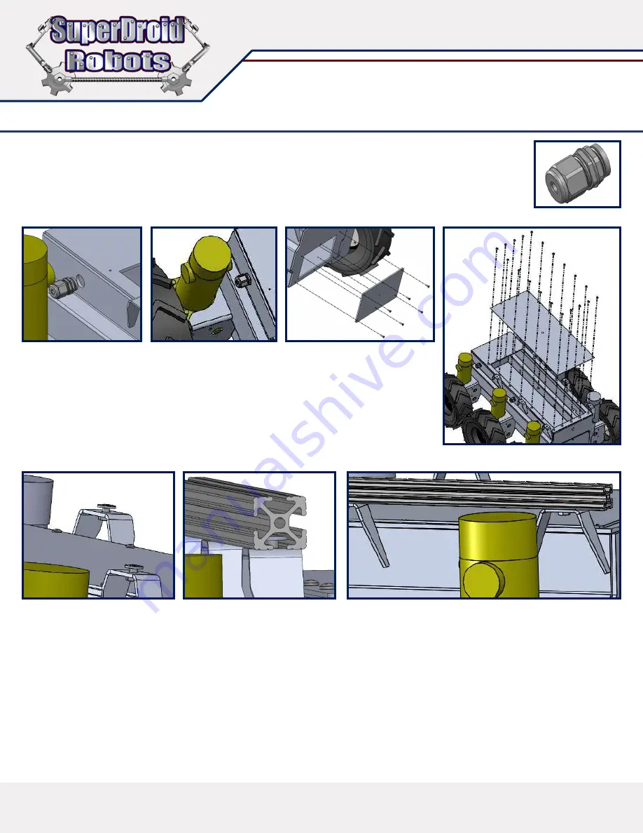
Install cord grips for the motor cables to enter the chassis. The cord grip has a nut that turns off the back end
of the grip housing (
Figure 5A
) . Remove the cord grip nut and insert cord grip into the chassis holes located
near the motor (
Figure 5B
). Screw on the nut from the inside of the chassis to lock cord grip in place (
Figure
5C
). Feed motor cable through cord grip and tighten down the cord grip cap until snug.
6.
Use provided hardware to install rear cover. (
Figure 6
)
7.
Use lid screws to install chassis lid. (
Figure 7
)
Figure 5B
Figure 7
Figure 5C
Figure 6
Figure 5A
8.
Mount 80/20 rails. Insert ¼-20 bolts from the bottom side of the rail brackets, and
loosely screw into the T-slot nut (
Figure 8A
). Slide the rail onto the bracket ensuring the
nut rides inside the groove of the rail (
Figure 8B
). Once the rail is resting on all three
brackets, adjust the position of the rail to the desired location. Tighten down nuts to hold
rail in place (
Figure 8C
). Repeat to other side.
9.
The mounting of any additional components will require the use of basic hand tools for
drilling and mounting. Be sure to place the object in position before creating any
permanent changes to the chassis. This allows the opportunity to check for ease of
placement, or any interference the component may have with active parts of the robot.
Figure 8A
Figure 8B
Figure 8C


