13
10.0.
REPLACEMENT PARTS
10.1. ORDERING
Because this manual covers a full series of units it is
impractical to provide a full list of replacement parts. To
order a part not listed in this manual, provide the unit
model number, serial number, and date code.
Reference the part by schematic reference symbol,
description and part number if available.
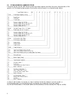
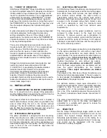
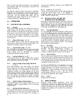
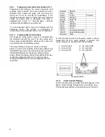
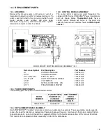
10.2. CONTROL MODULE ASSEMBLY
The same control modules are used throughout this
standard CRA Series STABILINE
®
Power Conditioners
and are shown below.
Tropicalized units
have a
similar control module but some of the parts are
specially treated and therefore have a
different part
number
.
FLOOR MOUNT CONTROL MODULE ASSEMBLY (A1)
Reference Symbol Part Description
Part Number
A1
CONTROL MODULE
213243-010
A1-A1
CONTROL BOARD
227412-001
A1-F1,F2,F3,F4
FUSE, 1A, 600V
213274-001
A1-LP1,LP2
LIGHT, INDICATOR, GREEN
227571-001
A1-M1
VOLTMETER
212917-001
A1-S1
SWITCH, ROCKER ON/ - /ON
227572-002
A1-T1
TRANSFORMER, POWER
227608-001
10.3. POWER COMPONENTS
The following parts are specific to each model number.
MODEL
NUMBER
T1 (EACH DECK)
POWERSTAT,
VARIABLE
TRANSFORMER
REPLACEMENT
BRUSH
ASSEMBLY
FOR T1
CRA141S010
150548-002
017702-004
10.4. REPLACEMENT BRUSH ASSEMBLY
Each POWERSTAT
®
Variable Transformer contains a durable brush assembly. These assemblies are designed to
reduce the need for attention or replacement; however, because these are moving parts that rely on contact friction
to operate properly, an annual inspection is suggested. Refer to the maintenance section of this manual for details.
Part number for a replacement brush assembly is listed in the table above.


