7
If remote sensing is desired, move the wire connected
to terminal 6 to terminal 7 and the wire connected to
terminal 8 to terminal 9 on the control module terminal
panel. This will disconnect the control module sense
terminals from the output terminals of the regulator.
Connect remote sensing wires to terminals 6 and 8 on
the control modules.
6.0.
OPTIONS
6.1. NON DESIGNATED OPTIONS
6.1.1.
Auxiliary Power Modules
(A2)
These modules are provided on units where a 120 volt
AC source is required to operate internal circuitry. The
output voltage of these modules is on terminals 1 and 2
of the terminal strip. If there is no output on these
terminals check the two fuses mounted on the same
bracket. The output of the auxiliary power modules are
used to operate fans, trip or hold on circuit breakers,
and on any other applications where 120 volts is
required.
6.1.2.
Fans
(B2)
On larger units fans are provided to help efficiently
remove heat generated in the cabinet. An auxiliary
power module supplies the fan operating voltage. If the
fans do not operate insure the auxiliary power module
output voltage is present.
6.2.
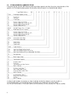
MODEL NUMBER SPECIFIED OPTIONS
6.2.1.
Circuit Breaker
(CB1)
An input circuit breaker provides short circuit and
overload protection for the CRA Series Power
Conditioners. Industrial circuit breakers with high
interrupting capacity are used. These breakers also
serve as an on/off switch for the regulator and any load
attached.
6.2.1.1. Shunt Trip
In units where the model number designates the circuit
breaker as “CS” the circuit breaker is equipped with a
shunt trip. A shunt trip causes the breaker to open when
voltage is applied to the shunt trip coil. The trip coil is
rated 120 volt, AC and is de-energized when the
breaker opens.
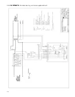
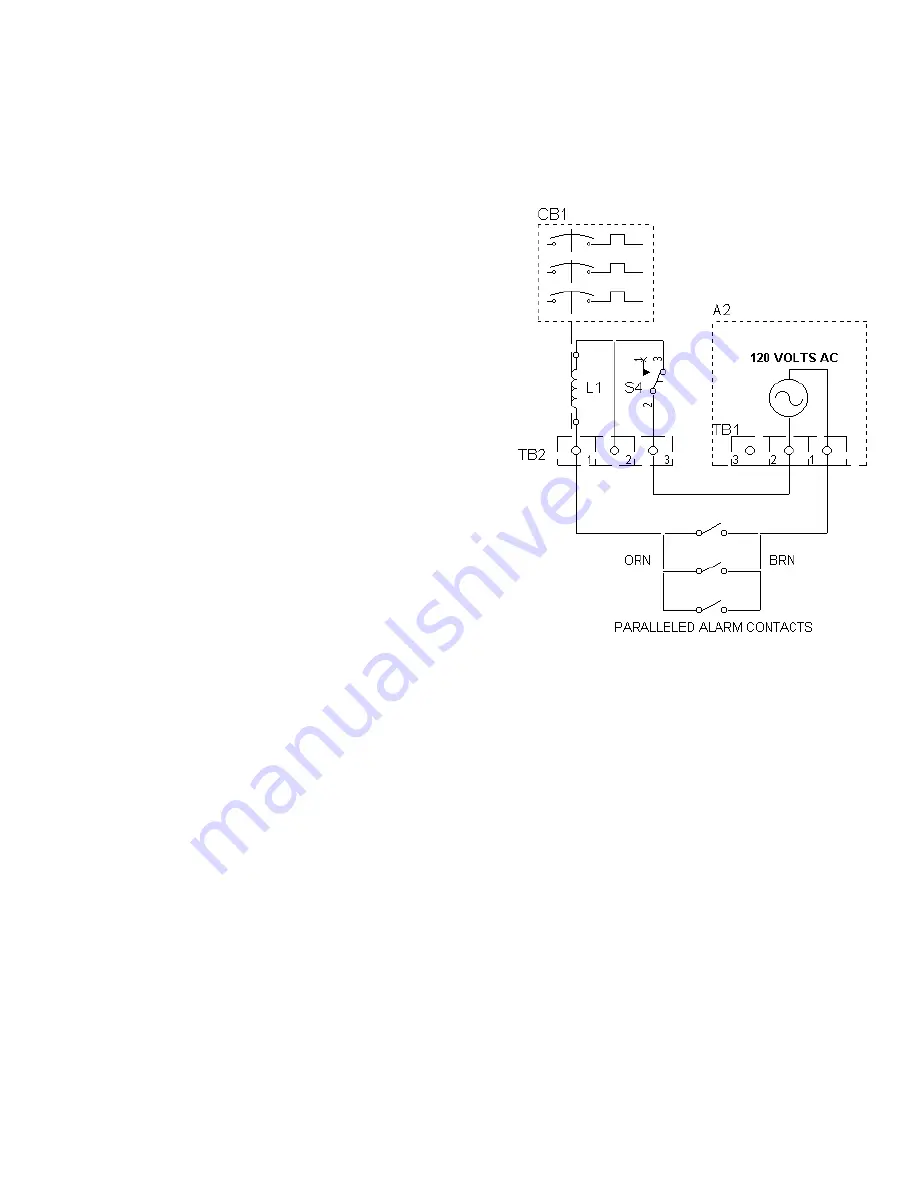
When alarm contact options and a circuit breaker trip
option are ordered together, the unit is furnished with
120 volt AC, auxiliary power module (A2) and the alarm
circuit contacts are wired to trip the input breaker. The
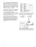
Shunt Trip Connections Diagram shows the typical
connections.
If you do not want the alarm contacts to trip the input
breaker, the unit can easily be re-configured to not trip
the breaker and to perform other control functions. The
120 volts supplied by the auxiliary power module to trip
the shunt coil can be replaced by an external source if
desired, but do not disconnect any other devices from
this source. A momentary push button switch (S4) is
provided to disable any alarm contacts from activating
the trip coil. This allows turn on of the system so alarm
options can reset. Hold switch in while turning on the
circuit breaker.
Shunt Trip Connections Diagram
6.2.2.
Manual Bypass Switch
(S3)
A two-position, non-load break, manual bypass switch
provides a nominal output voltage in the even of an
internal component failure. In the "REGULATOR"
position, the units regulating and transient suppression
components are active providing a conditioned output.
In the "BYPASS" position the regulating variable
transformer, motor power and transient suppression
circuits are disconnected from the isolation transformer.
The input power is connected to the nominal input tap
on the isolation transformer’s primary. This provides
nominal isolated voltage to the load. The neutral or
second input line, having no control components in
series, is not switched. The circuit breaker and isolation
transformer remain in line regardless of the bypass
switch position, since they are always needed. The
control unit’s voltmeter will continue to show the output
voltage, as long as the range switch is not in the off
position, but no correction is performed.
6.2.3.
Ammeters
(M1)
An analog ammeter displays load current for each
phase. Each meter indicates the load current within 2%
of the meters full range.


