Introduction
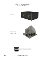
Congratulations on your purchase of the CM208W series subwoofers. These subwoofers feature (2) long-
throw 8” drivers capable of response down to 35Hz with a peak SPL capability of 112dB per cabinet. These
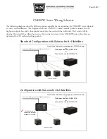
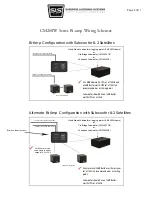
subwoofers also feature a flexible input and output feature set that allows use with all of our wall and ceiling
mount full range speakers. This Guide serves as an overview and provides useful hints regarding your
subwoofer installation and use. Please read in its entirety before proceeding.
Safety Responsibilities and Liability
All information in this guide is meant only for the purpose of rigging using the SLS supplied hardware. All
other rigging is considered part of the venue and/or end-user supplied equipment and is not addressed in
this guide. SLS assumes that a working knowledge of accepted rigging practices and safety will be applied to
all rigging materials and practices employed. This guide is not a comprehensive source for rigging in general.
The user must assume all responsibility for the appropriate use of SLS supplied rigging hardware and follow
at a minimum all applicable laws and regulations in force for each venue.
The weakest component determines the safety of the entire rigging assembly. Prior to installing, always
inspect all hardware components for wear, deformations, corrosion and missing or damaged parts. Also
inspect the venue attachment points for wear and confirm that the points are suitably load rated for the
equipment.
No information contained in this guide is intended as a warranty on the part of SLS. Anyone using this
information assumes all liability arising from it’s use. Product abuse, use of the product not in accordance
with SLS instructions or use in an application which the product has not been designed for is not covered
under any SLS warranty nor is SLS liable for any loss or damage.
Users in other countries should not assume that local regulations are based upon North American practices.
Users should consult with local regulatory authorities for specific codes and/or guidelines.
Replacement Parts
All defective components should be replaced with an SLS approved part. Contact the factory directly at
(417) 883-4549 to obtain approved replacement parts. SLS is not responsible for problems caused by using
non SLS supplied parts for the SLS supplied portion of the rigging.
Page 2 of 11

