Premier VS Infrared Heating System
Page 63
June 04, 2014
COMMISSIONING
Part 1
- Installation Checklist
Before proceeding with the start-up of the system, review the list of items below to ensure proper operation.
Close all open ended “S” hooks and turnbuckles to avoid unlocking chain with inadvertent contact
Verify that the Burners are correct for the fuel being burned. The rating plate listing this information is
located on the Burner housing, check this against your site plans.
Burners are position dependent. For proper operation, ensure that the Burner labeled as ‘No. 1’ on the
housing is located at the end of each Radiant Branch. Subsequent Burners in each Branch must be
positioned sequentially.
Burners should be mounted with the Burner casting as far back in the Tube opening as possible. Ensure
that little or no Tube is in view thru the viewing window.
Ensure that the End Vent Cap is oriented with the ¼” test hole at the 12 o’clock position and that it has
been secured to the end of each Branch with a #8 x 3/8” screw.
If you have both hot rolled Tube (black & shiny) and heat-treated aluminized steel Tube (matte gray),
ensure that the heat-treated aluminized Tube is used in the Tailpipe section of the system, and used in the
10 ft (3 m) following all Burners with a rating of 150,000 BTU/HR or higher.
Ensure that Tubes are fully inserted in the Couplings and tightened with band clamp hardware at the 10 or
2 o’clock position. Tighten band clamps alternately to prevent buckling of the Coupling sleeve.
Ensure that each Branch has a Damper Coupling at the end of the Radiant length, as well as one at the
Vacuum Pump. If the system is symmetrical, one Damper along the Common Tailpipe may be used.
Single Rate Systems will use standard Manual Dampers while Modulating Rate Systems will use
Motorized Dampers.
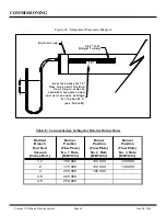
Ensure that Reflectors are properly overlapped and that every second overlap joint is screwed together, as
shown in Figure 9. The remaining joints are left loose. This will allow the Reflectors to ‘telescope’ with
the thermal expansion of the System.
Visually confirm that the Vacuum Pump’s impeller rotates in the same direction indicated by the arrow on
the pump scroll. To reverse the rotation, see instructions on the motor.
Ensure that EACH Flexible Gas Connector is of sufficient size for the desired Burner rate and is installed
in a smooth arc with no kinks. For Burners firing at 150,000 BTU/hr and higher ¾” dia. x 36” Gas Flex
Connector is required.
Purge Gas Lines of all air.
Verify the Wiring & that the Electrical Power Supply is connected but remains turned OFF.


