Superiorfireplaces.US.com
126741-01C
7
PRE-INSTALLATION PREPARATION
Continued
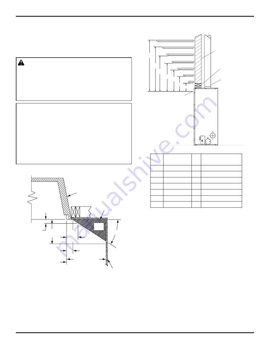
MANTEL CLEARANCES
Figure 8 shows projected mantel depths at various heights above
top of louver opening. Figure 7, shows minimum allowable distances
from various mantel components in relation to both sides of fireplace
opening.
WARNING: When finishing appliance do not overlap
combustible materials onto the black front face. Brick,
tile or other noncombustible materials may be applied
to the face provided that any fireplace openings are
not blocked and gaps in the material used and the face
are sealed with a noncombustible caulking.
NOTICE: NFPA 54 defines minimum space require-
ments for the installation of this appliance. This
fireplace must be installed in an unconfined space
with a minimum of 50 cubic feet per 1,000 BTUs of
gas output. Therefore 36” models require 2,650 cu-
bic feet, 42” models require 3,100 cubic feet. If the
space you wish to install the fireplace does not meet
these requirements NFPA 54 details several actions
that may be taken.
Figure 9 - Clearances for Combustible Mantels
Figure 8 - Side Clearances for Combustible Mantels
1
1
/
2
"
(3.8 cm)
3
1
/
2
"
(8.9
cm)
Outer
Surround
Combustible
Material May
Be Used
Perpendicular
Side Wall
5
1
/
4
"
(13.3 cm)
1
3
/
4
"
(4.4 cm)
To Fireplace
Opening
10" (25.4 cm)
33°
Safe
Zone
Ref. Mantel Depth Ref.
Mantel from Top of
Louver Opening
1
16" (40.6 cm)
A
18" (45.7 cm)
2
14" (35.6 cm)
B
16" (40.6 cm)
3
12" (30.5 cm)
C
14" (35.6 cm)
4
10" (25.4 cm)
D
12" (30.5 cm)
5
8" (20.3 cm)
E
10" (25.4 cm)
6
4" (10.2 cm)
F
8" (20.3 cm)
7
2" (5.1 cm)
G
6" (15.2 cm)
C
B
A
D
E
F
G
Top of Louver
Opening
3
2
1
4
5
6
7
Stud Wall
4" B-Vent
Flue Pipe
2 x 4 Header
at 1" Min.
Clearance


