Installation & Operation Manual
O-360 and IO-360 Series Engines
24 Chapter 3 • Aircraft / Engine
© March 2004 Superior Air Parts Inc. Integration Considerations
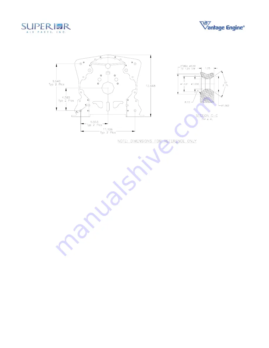
Figure 3-6 • Conical Mount Dimensions
B. Engine CG and Moment of Inertia
The engine weight and location of the center of
gravity are specified in Table 7 of the Model
Specification Data. Definitions for the variables
used in Table 7 are illustrated in Figure 3a. & 3b.
of the Model Specification Data. Moments of
inertia are defined in Table 8 of the Model
Specification Data.
The location of the center of gravity is defined
with respect to the crankshaft centerline (lateral
and vertical dimensions) and with respect to the
crankcase backplane for the longitudinal
dimension. This data, together with the
appropriate data for additional components
such as propeller assembly, oil cooler, and other
engine and engine mount supported items
provide sufficient information to locate the center
of gravity with respect to the airframe.
C. Engine Mount Design Loads
Superior Vantage Engines are certified to meet
the requirements of FAR 23 Acrobatic Category
load factors for most engine and propeller
combinations. Table 3-3 lists the limit and
ultimate load limits for the engine
.
The term “maneuvering moment” of Table 3-3
relates to the force-couple or moment produced
by the weight of the engine, propeller and
accessories attached directly to the engine and
the distance from the center of gravity of that
assembly to the backplane of the crankcase.
These values represent the maximum moments
(limit and ultimate) that may be imposed on the
engine mount structure.


