15
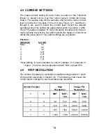
Figure 4.1
Switches For Setting Current Level
And Step Resolution
4.7 SIGNAL SPECIFICATIONS
4.7.1 Connector Pin Assignments
All connections are made via the 5-pin connector, part number
221536-005.
Pin
Assignment
1
OPTO
2
PULSE
3
DIR
4
AWO
5
RDCE
4.7.2 Signal Descriptions
OPTO
Opto-Isolator Supply
User supplied power for the opto-isolators.
PULSE Pulse Input
A low to high transition on this pin advances the motor one
step. The step size is determined by the Step Resolution
switch setting.
DIR
Direction Input
Summary of Contents for SLO-SYN SS2000MD7
Page 1: ...INSTALLATION INSTRUCTIONS for SLO SYN MODELS SS2000MD7 SS2000MD7 128 TRANSLATOR DRIVE ...
Page 17: ...17 Suggested Methods For Control Interface Figure 4 2 ...
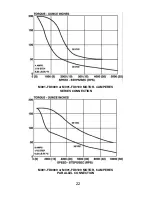
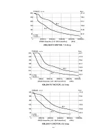
Page 20: ...20 M062 LE09 MOTOR 3 AMPERES SERIES CONNECTION M062 LE09 MOTOR 6 AMPERES PARALLEL CONNECTION ...
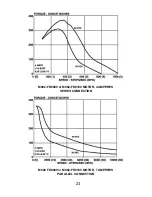
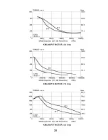
Page 21: ...21 M063 LE09 MOTOR 3 AMPERES SERIES CONNECTION M063 LE09 MOTOR 6 AMPERES PARALLEL CONNECTION ...
Page 25: ...25 ...
Page 26: ...26 ...
Page 27: ...27 ...
Page 28: ...28 ...


