18
4.8 INDICATOR LIGHTS
"POWER" LED, Red
Lights when the drive logic power supply is present, indicating that
the drive is energized.
"FAULT" LED, Red
Lights to indicate over current condition. This condition is a result
of motor wiring errors or a ground fault.
Also lights to indicate the heat sink temperature has exceeded a
safe level for reliable operation.
Recovery from over current or over temperature condition requires
removing and then reapplying the power.
SECTION 5: TORQUE VERSUS SPEED CHAR-
ACTERISTICS
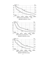
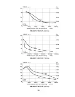
5.1 MOTOR PERFORMANCE
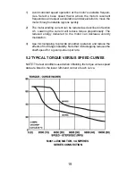
All stepper motors exhibit instability at their natural frequency and
harmonics of that frequency. Typically, this instability will occur at
speeds between 50 and 1000 full steps per second and, depending on
the dynamic motor load parameters, can cause excessive velocity
modulation or improper positioning. This type of instability is represented
by the open area at the low end of each Torque vs. Speed curve.
There are also other instabilities which may cause a loss of torque at
stepping rates outside the range of natural resonance frequencies. One
such instability is broadly defined as mid-range instability. Usually, the
damping of the system and acceleration/deceleration through the reso-
nance areas aid in reducing instability to a level that provides smooth
shaft velocity and accurate positioning. If instability does cause
unacceptable performance under actual operating conditions, the
following techniques can be used to reduce velocity modulation.
Summary of Contents for SLO-SYN SS2000MD7
Page 1: ...INSTALLATION INSTRUCTIONS for SLO SYN MODELS SS2000MD7 SS2000MD7 128 TRANSLATOR DRIVE ...
Page 17: ...17 Suggested Methods For Control Interface Figure 4 2 ...
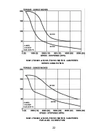
Page 20: ...20 M062 LE09 MOTOR 3 AMPERES SERIES CONNECTION M062 LE09 MOTOR 6 AMPERES PARALLEL CONNECTION ...
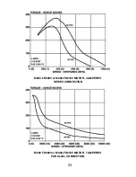
Page 21: ...21 M063 LE09 MOTOR 3 AMPERES SERIES CONNECTION M063 LE09 MOTOR 6 AMPERES PARALLEL CONNECTION ...
Page 25: ...25 ...
Page 26: ...26 ...
Page 27: ...27 ...
Page 28: ...28 ...


