background image

3

THINGS TO KNOW BEFORE USING THIS
EQUIPMENT


Only qualified personnel should install or perform servicing
procedures on this equipment. Do not operate the unit without the
enclosures in place as voltage present in this unit can cause
serious or fatal injury.


Before performing any work on the unit, allow at least five minutes
for the capacitors to discharge fully.


Voltage is present on unprotected pins when unit is operational.


The "PWR ON" LED must be off for approximately 30 seconds
before making or breaking the motor connections.


Motors powered by this drive may develop extremely high torque.
Be sure to disconnect power to this drive before doing any
mechanical work.

CAUTION:
This unit is designed for 24 to 75 Vdc input only (see Section
4.2, Electrical Specifications, Page 11).

WARRANTY RESTRICTIONS

Reconfiguration of the circuit in any fashion not shown in this manual will
void the Warranty.

Failure to follow the installation guidelines as described in Section 3 will
void the Warranty.

SECTION 1: INTRODUCTION

1.1 USING THIS MANUAL

It is important that you understand how this SLO-SYN SS2000MD7
Translator/Drive is installed and operated before you attempt to use it.

We strongly recommend that you read this manual completely
before proceeding with the installation of this unit.

Summary of Contents for SLO-SYN SS2000MD7

Page 1: ...INSTALLATION INSTRUCTIONS for SLO SYN MODELS SS2000MD7 SS2000MD7 128 TRANSLATOR DRIVE ...

Page 2: ...And Pin Assignments 7 SECTION 4 SPECIFICATIONS 11 4 1 Mechanical Specifications 11 4 2 Electrical Specifications 11 4 3 Environmental Specifications 12 4 4 Motor Compatibility 12 4 5 Current Settings 14 4 6 Step Resolution 14 4 7 Signal Specifications 15 4 8 Indicator Lights 18 SECTION 5 TORQUE VERSUS SPEED CHARACTERISTICS 18 5 1 Motor Performance 18 5 2 Typical Torque Vs Speed Curves 19 SECTION 6...

Page 3: ...owered by this drive may develop extremely high torque Be sure to disconnect power to this drive before doing any mechanical work CAUTION This unit is designed for 24 to 75 Vdc input only see Section 4 2 Electrical Specifications Page 11 WARRANTY RESTRICTIONS Reconfiguration of the circuit in any fashion not shown in this manual will void the Warranty Failure to follow the installation guidelines ...

Page 4: ...rate properly Appendix A provides procedures for troubleshooting electrical inter ference problems 1 2 PRODUCT FEATURES The SLO SYN SS2000MD7 MD7 128 Translator Drive is a bipolar speed adjustable two phase PWM drive which uses power MOSFET devices The MD7 can be set to operate a stepper motor in 1 2 1 10 1 25 or 1 100 microsteps The MD7 128 can be set to operate a stepper motor in Full 1 16 1 64 ...

Page 5: ...tible with the drive Refer to Section 4 4 for a list of compatible motors 2 Set the correct current level for the motor being used per the instructions in Section 4 5 Heat sinking is required if a current of 4 amperes or higher is used 3 Select the appropriate step resolution and set the switches as described in Section 4 6 4 Wire the motor per the Motor Connections description in Sec tion 3 2 5 C...

Page 6: ...oo much Figure 3 1 Mounting Diagram NOTE Case temperature should not exceed 70º C 158º F A heat sink such as Superior Electric Heat Sink Assembly 221576 001 must be used when the drive is operated at a current setting of 4 amperes or more In this case the unit should be mounted upright with the cooling fins vertical or proper cooling will not occur Air flow should not be obstructed Forced air cool...

Page 7: ...closure to shield it and its wiring from electrical noise sources If this cannot be done keep the drive at least three feet from any noise sources 3 2CONNECTOR LOCATIONS AND PIN ASSIGN MENTS Figure 3 2 shows the connector locations for the SLO SYN SS2000MD7 Translator Drive Figure 3 2 Connector Locations MOTOR CONNECTIONS ...

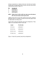
Page 8: ...nd M5 The motor frame must be grounded Cabling from the drive to the motor should be done with a shielded twisted pair cable As a guideline the wires for each motor phase should be twisted about six times per foot Superior Electric offers the following motor cable configurations These cables have unterminated leads on both ends Length Part Number 10 ft 3 m 216022 031 25 ft 7 6 m 216022 032 50 ft 1...

Page 9: ...TORS D F B H 5 4 1 3 GREEN WHITE RED RED 6 LEAD MOTORS WHITE N C E 2 G N C BLACK WHITE GREEN D F B H 5 4 1 3 WHITE BLACK WHITE RED RED 8 LEAD MOTORS SERIES CONNECTIONS G BLACK A WHITE ORANGE E GREEN C WHITE GREEN 6 2 7 8 DRIVE PIN 1 DRIVE PIN 2 DRIVE PIN 1 DRIVE PIN 2 DRIVE PIN 1 DRIVE PIN 2 DRIVE PIN 4 DRIVE PIN 3 DRIVE PIN 4 DRIVE PIN 3 DRIVE PIN 4 DRIVE PIN 3 D F B H 5 4 1 3 WHITE RED RED 8 LEA...

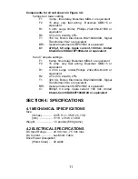
Page 10: ...mportant that capacitor C1 be connected within three feet 0 9 meter of the input terminals The capacitor must be of the correct value and have the proper current and voltage parameters see list of components on page 11 It is recommended that the power supply leads be twisted together 6 twists per foot NOTE If the power supply is grounded it must only be grounded on the negative side or the short c...

Page 11: ...ettings F1 6 amp time delay Bussman MDA 6 or equivalent F2 15 amp very fast acting Bussman GBB 15 or equivalent R1 4 ohm surge limiter Phillips 2322 654 61408 or equivalent R2 4 7k ohm 2 watts 5 T1 320 VA Bicron Electronics BU233AS040D Signal Transformer 80 4 or equivalent BR1 General Instrument GBPC3502 or equivalent C1 6800µf 9 4 amp ripple current 100 Vdc United Chemi Con 36DA682F100AD2A or equ...

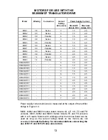
Page 12: ...TIBILITY Motor Types Superior Electric M and KM Series Frame Sizes M Series M061 NEMA 23D through M092 NEMA 34 KM series KML060 NEMA 23 through KML093 NEMA 34 Number of Connections 4 6 8 Minimum Inductance 1 millihenry Maximum Resistance 0 25 x Vdc Supply I Setting Example Vdc 60 I Setting 7 R max 0 25 x 60 7 2 1 ohms NOTE Maximum resistance is total of motor plus cable CAUTION Do not use larger f...

Page 13: ... 0 2 0 KML061F05 3 1 0 2 0 KML062F07 3 1 0 3 5 KML062F13 6 1 5 4 5 KML063F07 3 1 0 2 0 KML063F13 7 2 0 4 5 KML091F07 4 1 5 2 5 KML091F13 6 1 5 4 0 KML092F07 4 2 0 2 0 KML092F13 7 2 0 4 5 KML093F07 4 2 0 2 0 KML093F14 7 2 0 4 5 Power supply currents shown are measured at the output of the rectifier bridge in Figure 3 4 M061 M062 and M063 motors listed include LS LE CS FC and FD versions M091 M092 a...

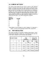
Page 14: ...s are ON the one which selects the highest current level will be the active switch The switch settings are as follows Position amperes Current None 1 0 1 2 0 2 3 0 3 4 0 4 5 0 5 6 0 6 7 0 Heat sinking is recommended at current settings of 4 amperes or higher The drive case temperature MUST NOT exceed 70ºC 4 6 STEP RESOLUTION The number of pulses per revolution is selected using positions 7 and 8 o...

Page 15: ... the 5 pin connector part number 221536 005 Pin Assignment 1 OPTO 2 PULSE 3 DIR 4 AWO 5 RDCE 4 7 2 Signal Descriptions OPTO Opto Isolator Supply User supplied power for the opto isolators PULSE Pulse Input A low to high transition on this pin advances the motor one step The step size is determined by the Step Resolution switch setting DIR Direction Input ...

Page 16: ... The motor current will be 50 of the selected value when this signal is low Caution Holding torque will also be reduced when this signal is low NOTE If you are using the drive with an SS2000I or SS2000I V control the READY input and the OPTO input on the control must be jumpered together 4 7 3 Level Requirements OPTO Voltage 4 5 to 6 0 volts dc Current 16 mA per signal used Other Signals Voltage L...

Page 17: ...17 Suggested Methods For Control Interface Figure 4 2 ...

Page 18: ... instability will occur at speeds between 50 and 1000 full steps per second and depending on the dynamic motor load parameters can cause excessive velocity modulation or improper positioning This type of instability is represented by the open area at the low end of each Torque vs Speed curve There are also other instabilities which may cause a loss of torque at stepping rates outside the range of ...

Page 19: ...ng the current will reduce torque proportionally The reduced energy delivered to the motor can decrease velocity modulation 3 Use microstepping to provide smoother operation and reduce the effects of mid range instability Note that microstepping reduces the shaft speed for a given pulse input rate 5 2 TYPICAL TORQUE VERSUS SPEED CURVES NOTE The test conditions used when obtaining the torque versus...

Page 20: ...20 M062 LE09 MOTOR 3 AMPERES SERIES CONNECTION M062 LE09 MOTOR 6 AMPERES PARALLEL CONNECTION ...

Page 21: ...21 M063 LE09 MOTOR 3 AMPERES SERIES CONNECTION M063 LE09 MOTOR 6 AMPERES PARALLEL CONNECTION ...

Page 22: ...22 M091 FD8009 or M091 FD8109 MOTOR 4 AMPERES SERIES CONNECTION M091 FD8009 or M091 FD8109 MOTOR 6 AMPERES PARALLEL CONNECTION ...

Page 23: ...23 M092 FD8009 or M092 FD8109 MOTOR 4 AMPERES SERIES CONNECTION M092 FD8009 or M092 FD8109 MOTOR 7 AMPERES PARALLEL CONNECTION ...

Page 24: ...24 M093 FD8114 or M093 FD8014 MOTOR 5 AMPERES SERIES CONNECTION M093 FD8114 or M093 FD8014 MOTOR 7 AMPERES PARALLEL CONNECTION ...

Page 25: ...25 ...

Page 26: ...26 ...

Page 27: ...27 ...

Page 28: ...28 ...

Page 29: ...he motor If installation and operating instructions have been followed carefully this unit should perform correctly If the motor fails to step properly the following checklist will be help locate and correct the problem In General Check all installation wiring carefully for wiring errors or poor connections Check to see that the proper voltage levels are being supplied to the unit Be sure that the...

Page 30: ...o low in value IF TORQUE IS LOW Check For All Windings Off active or Reduced Current active Improper supply voltage IF POWER INDICATOR IS NOT LIT Check For Improper input wiring and voltage levels Blown supply circuit fuse or tripped input circuit breaker IF FAULT INDICATOR IS LIT Check For Improper motor wiring Grounded or shorted wiring to the motor or shorted motor Improper motor type or incorr...

Page 31: ...ems exist use appropriate line conditioning such as line filters or isolation transformers 2 Be certain proper wiring practices are followed for location groun ding wiring and relay suppression 3 Double check the grounding connections to be sure they are good electrical connections and are as short and direct as possible 4 Try operating the drive with all suspected noise sources switched off If th...

Page 32: ... IN LIEU OF ANY OTHER WARRANTIES EXPRESS OR IMPLIED INCLUDING WITHOUT LIMITATION ANY IMPLIED WARRANTY OF MERCHANTABILITY OR FITNESS FOR A PARTICULAR PURPOSE and of any other obligations or liabilities on the part of the Company and no person is authorized to assume for the Company any other liability with respect to equipment manufactured by the Company The Company shall have no liability with res...

Reviews: