6
SECTION 3: INSTALLATION GUIDELINES
3.1 MOUNTING
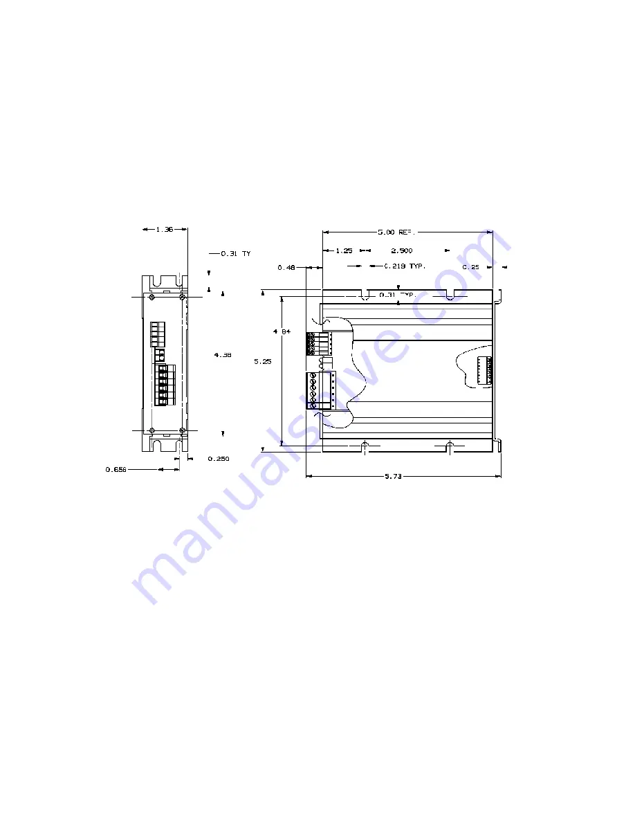
The SLO-SYN Drive is mounted by fastening its mounting brackets to a
flat surface as shown in Figure 3.1. If the Heat Sink Assembly, part
number 221576-001, is mounted against a bulkhead, be sure to apply a
thin coating of thermal compound between the heat sink and the
mounting surface before fastening the unit in place. Do not use too much
thermal compound. It is better to use too little than too much.
Figure 3.1, Mounting Diagram
NOTE: Case temperature should not 70º C (+158º F). A
heat sink, such as Superior Electric Heat Sink Assembly
221576-001, must be used when the drive is operated at a
current setting of 4 amperes or more. In this case the unit
should be mounted upright (with the cooling fins vertical)
, or proper cooling will not occur. Air flow should not be
obstructed.
Forced air cooling may be required to maintain
temperature within the stated limits.
When selecting a mounting location, it is important to leave at least two
inches (51mm) of space around the top, bottom and sides of the unit to
allow proper airflow for cooling.
Summary of Contents for SLO-SYN SS2000MD7
Page 1: ...INSTALLATION INSTRUCTIONS for SLO SYN MODELS SS2000MD7 SS2000MD7 128 TRANSLATOR DRIVE ...
Page 17: ...17 Suggested Methods For Control Interface Figure 4 2 ...
Page 20: ...20 M062 LE09 MOTOR 3 AMPERES SERIES CONNECTION M062 LE09 MOTOR 6 AMPERES PARALLEL CONNECTION ...
Page 21: ...21 M063 LE09 MOTOR 3 AMPERES SERIES CONNECTION M063 LE09 MOTOR 6 AMPERES PARALLEL CONNECTION ...
Page 25: ...25 ...
Page 26: ...26 ...
Page 27: ...27 ...
Page 28: ...28 ...


