
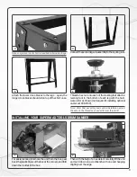
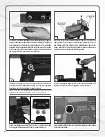
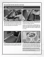

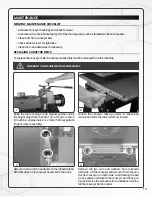

Unscrew
the bolts holding the wooden packing support
to the underside of the unit and then carefully swing the
unit around on the bench and repeat for the wooden
support at the opposite end (these bolts can be re-used
to secure the unit to the stand in step #5; extra bolts are
also provided for this with the machine).
With the help of an assistant place the unit on its stand
taking care to line up the mounting holes in the top of
the stand with the holes in the underside of the unit’s
base, and then remove the Styrofoam and wooden sup-
port block from under the sanding head.
3
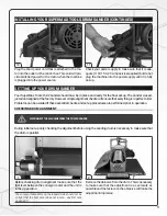
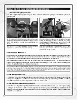
Using the supplied 14 mm wrench bolt the machine to
the stand from underneath using one of the supplied
hex bolts and flat washers in each corner.
Note: With the unit properly secured, level the stand and
tighten all its fasteners with a 1/2" or 13 mm socket.
Screw the height adjustment knob into the handle and
tighten it down with the supplied 14 mm wrench.
5
6
10
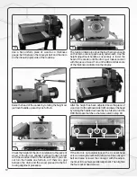
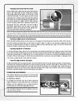
Slide the digital read-out (DRO) from its slot and install
the supplied batteries with the (+) side facing up.
Re-install the
DRO fully into the slot and plug in the cable
from the machine.
7
8
9
4
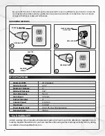
LIFTING POINT
LIFTING POINT
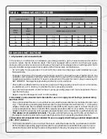
Motor
Drum carriage
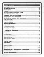
Summary of Contents for 16-32
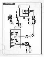
Page 23: ...23 16 32 WIRING DIAGRAM...
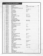
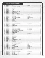
Page 26: ...16 32 HEAD ASSEMBLY 26...
Page 29: ...NOTES 29...
Page 30: ...P 1 888 454 3401 F 1 651 454 3465 SuperMaxTools com sales SuperMaxTools com...


