background image

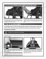
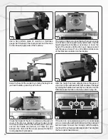
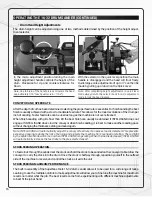
TENSION ROLLER CONTACT ADJUSTMENT 


The tension rollers are factory set for the most versatile use. 

1. 

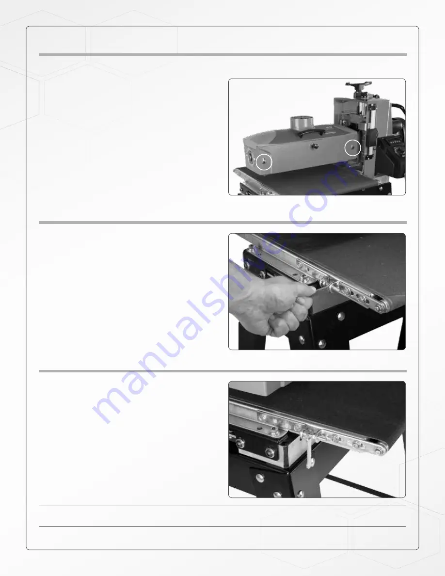
If necessary, to adjust tension roller contact, loosen 

the four socket head screws holding the tension rol-

ler brackets (two per side; front and back – shown 

in opposite picture). 

2. 

Have abrasive wrapped on drum. 

3. 

With machine unplugged, lower sanding drum until 

it rests on conveyor belt. 

4. 

Raise drum 2 to 3 revolutions. 

5. 

Tighten the four socket head screws (two per side; 

front and back). 

6. 

Raise drum up, off of the conveyor belt. 

7. 

Set drum for proper sanding height and process stock.

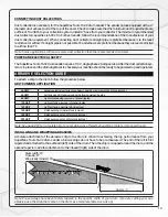
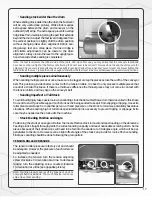
CONVEYOR BELT TENSION 


Insufficient belt tension will cause slippage of conveyor 

belt on the drive roller during sanding operation. The 

conveyor belt is too loose if it can be stopped by hand 

pressure applied directly to the top of the conveyor belt. 
Excessive belt tension can result in bent rollers, prema-

ture wearing of the bronze bushings or conveyor belt 
To adjust the tension of the conveyor belt, first adjust 

the take-up screw nut on both sides of the conveyor 

to obtain approximately equal tension on both sides of 

the belt when taut (see opposite picture). 

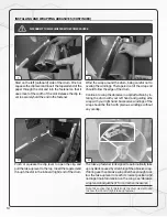
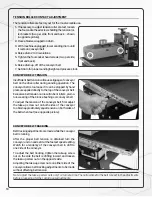
CONVEYOR BELT TRACKING 


Belt tracking adjustments are made while the conveyor 

belt is running. 
After the proper belt tension is obtained turn the 

conveyor unit on and set it at the fastest speed setting. 

Watch for a tendency of the conveyor belt to drift to 

one side of the conveyor. 
To adjust the belt tracking, tighten the take-up screw 

nut on the side the belt is drifting toward, and loosen 

the take-up screw nut on the opposite side. 
Adjusting the take-up screw nuts on either side of the 

conveyor allows belt-tracking adjustments to be made 

without affecting belt tension.

Note: Adjust the take-up screw nuts only 1/4 turn at a time. Then allow time for the belt to react to the adjustments 

before proceeding further. Avoid over-adjustments.

18

Summary of Contents for 16-32

Page 1: ...OWNER S MANUAL C US SuperMaxTools com sales SuperMaxTools com P 888 454 3401 F 651 454 3465 08 2017 SuperMax Tools 269049 16 32 DRUM SANDER...

Page 2: ...ts comparable to industrial size sanders at a fraction of the cost For future reference find the model stock and serial numbers on the back of machine base and write them in below Model Stock Number S...

Page 3: ...Wrapping Abrasives 13 Proper Abrasive Wrap Position 15 Abrasive Wrap Tension Adjustment 15 Maximizing Abrasive Longevity 15 operating your Drum Sander 15 Drum Depth of Cut 15 Conveyor and Speed Rate...

Page 4: ...REACH Keep proper footing and balance at all times 14 MAINTAIN TOOLS WITH CARE Keep tools sharp and clean for best and safest performance Fol low instructions for lubricating and changing ac cessories...

Page 5: ...stood or if in doubt as to whether the tool is properly grounded Use only 3 wire extension cords that have 3 prong grounding plugs and 3 pole receptacles that ac cept the tool s plug Repair or replace...

Page 6: ...com be used with this tool If the tool must be reconnected for use on a different type of electric circuit the reconnection should be made by qualified service personnel and after reconnection the too...

Page 7: ...make an immediate inspection Ask for a damage or loss report Also notify your distributor of any loss or damage during shipment See enclosed Warranty Statement Note Before setting up make sure that th...

Page 8: ...own x 1 2 Stand leg x 4 3 Long lower cross braces x 2 4 Short lower cross braces x 2 5 Long top cross braces x 2 6 Short top cross braces x 2 7 Hardware bag x 1 8 Wrench 12 14 mm x 1 9 Allen key 4 5 m...

Page 9: ...own on a workbench with one end hanging slightly over the edge INSTALLING YOUR SUPERMAX TOOLS DRUM SANDER 1 2 Attach the lower cross braces to the legs again the longer cross braces should sit on top...

Page 10: ...ndthenremovetheStyrofoamandwoodensup port block from under the sanding head 3 Using the supplied 14 mm wrench bolt the machine to the stand from underneath using one of the supplied hex bolts and flat...

Page 11: ...ealignmentcheckswillensurethateverythingisinperfectorder Problems can be avoided if these essential checks and set up procedures are performed prior to operation CHECKING DRUM ALIGNMENT During initial...

Page 12: ...the height has been adjusted move the piece of wood over to the outboard side left and lower the head by turning the handle down exactly one full turn until the DRO thickness matches what was noted in...

Page 13: ...st requirements are sufficient To attach to your collection system install 4 hose from your collector The minimum recommended dust collector capacities is 600 cfm For best results follow the recommend...

Page 14: ...ail only the drum was removed to show the inboard right take up fastener 3 Start on the left outboard side of the drum Pinch or squeeze the clip lever and insert the tapered end of the paper through t...

Page 15: ...per depth of cut We recommend practicing on a scrap of wood prior to sanding a project Digital Read Out Operation Foraddedconvenienceadigitalreadout DRO forsandingthickness is included as standard equ...

Page 16: ...d rate to the pre selected speed STOCK FEEDING OPERATION To feed stock through the sander rest the stock and hold the stock to be sanded on the conveyor table Allow the conveyor to carry the stock int...

Page 17: ...ckness difference the thinner pieces may not come in contact with the tension rollers and may slip on the conveyor belt Sanding Imperfect or Tall Stock Toavoidbodilyinjurytakespecialcarewhensandingsto...

Page 18: ...t tension can result in bent rollers prema ture wearing of the bronze bushings or conveyor belt To adjust the tension of the conveyor belt first adjust the take up screw nut on both sides of the conve...

Page 19: ...carriage to its highest position using the height adjustment handle Turn off power source to machine Unplug main drive motor from receptacle in gear motor assembly Loosen the conveyor take up screws...

Page 20: ...ce with monofilament backing DRUM ABRASIVES 60 6036 36 Grit SuperMax Tools 16 32 4 Wraps in Box 60 6060 60 Grit SuperMax Tools 16 32 4 Wraps in Box 60 6080 80 Grit SuperMax Tools 16 32 4 Wraps in Box...

Page 21: ...ed Fig 5 Circuit fuse blown or circuit breaker tripped Replace fuse or retrip breaker after determining cause BRUSH MOTOR OVERLOADS Inadequate circuit Check electrical requirements Machine overloaded...

Page 22: ...LY Improper adjustment of height control Readjust height control KNOCKING SOUND WHILE RUNNING Bearing worn Replace bearing Contact distributor SNIPING OF WOOD GOU GING NEAR END OF BOARD Inadequate sup...

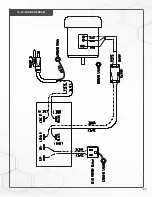
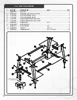
Page 23: ...23 16 32 WIRING DIAGRAM...

Page 24: ...D17 1 25 480BS 125 THRUSTBEARING 51103 1 26 71632 126 SHROUD 1 27 30 3028 STUD 4 28 71632 128 HEX CAP SCREW 3 8 16 X 3 4 8 29 480BS 129 FLATWASHER 3 8 8 30 480BS 130 HINGE 2 31 71632 131 DUSTCOVER 1 3...

Page 25: ...AP SCREW M6 X 1 0 X 30 1 84 71632 184 SOCKETHEAD CAP SCREW M6 X 1 0 X 15 1 85 71632 185 MICRO ADJUSTMENT QUICK LABEL 1 86 480BS 186 MAINTENANCE LABEL 1 87 480BS 187 WARNING LABEL 1 88 71632 188 SETSCR...

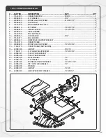
Page 26: ...16 32 HEAD ASSEMBLY 26...

Page 27: ...12 480BS 237 DRIVE ROLLER SUPPORTBRACKET 1 13 71632 213 CONVEYOR BED 1 14 480BS 239 SOCKETHEAD CAP SCREW 1 4 20 X 3 4 4 15 71632 215 CONVEYOR BELT NOTSHOWN 1 16 480BS 245 HEX NUT 5 16 18 2 17 71632 2...

Page 28: ...4 TOP CROSS BRACE SHORT 2 5 71632 305 LOWER CROSS BRACE RAIL LONG 2 6 71632 306 LOWER CROSS BRACE RAIL SHORT 2 7 480BS 507 FLANGE NUT 5 16 8 8 480BS 508 LEVELING FOOT 4 9 480BS 129 FLATWASHER 3 8 8 10...

Page 29: ...NOTES 29...

Page 30: ...P 1 888 454 3401 F 1 651 454 3465 SuperMaxTools com sales SuperMaxTools com...

Reviews: