
17
•
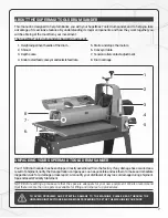
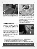
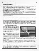
Sanding Imperfect or Tall Stock
To avoid bodily injury take special care when sanding stock that is twisted, bowed or otherwise varied in thickness
from end to end. If possible support such stock as it is being sanded to keep it from slipping or tipping. Use extra
roller stand, assistance from another person, or hand pressure on the stock to minimize potentially hazardous
situations. When sanding high or tall stock special attention is necessary to prevent tipping or slippage. Extra
care may be needed as the stock exits the machine.
•
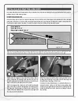
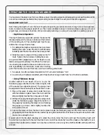
Stock Feeding Position and Angle
Positioning the stock at an angle will allow the most effective stock removal and least loading on the abrasives.
Feeding stock straight through yields the widest sanding capacity and least noticeable scratch pattern. Some
pieces because of their dimensions will need to be fed into the sander at a 90-degree angle, which will be per-
pendicular to the drum. However, even a slight offset angle of the stock can provide for more effective sanding.
Final pass sanding should be done following the grain pattern.
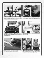
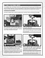
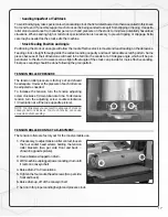
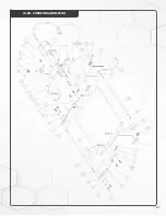
TENSION ROLLER PRESSURE
The tension roller pressure is factory set and should
be adequate. However, the pressure of each roller can
be adjusted as needed.
To increase the tension turn the tension adjusting
screw clockwise 1/4 revolution at a time. To decrease
tension turn the adjusting screw counter-clockwise
1/4 revolution at a time (see opposite picture).
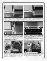
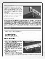
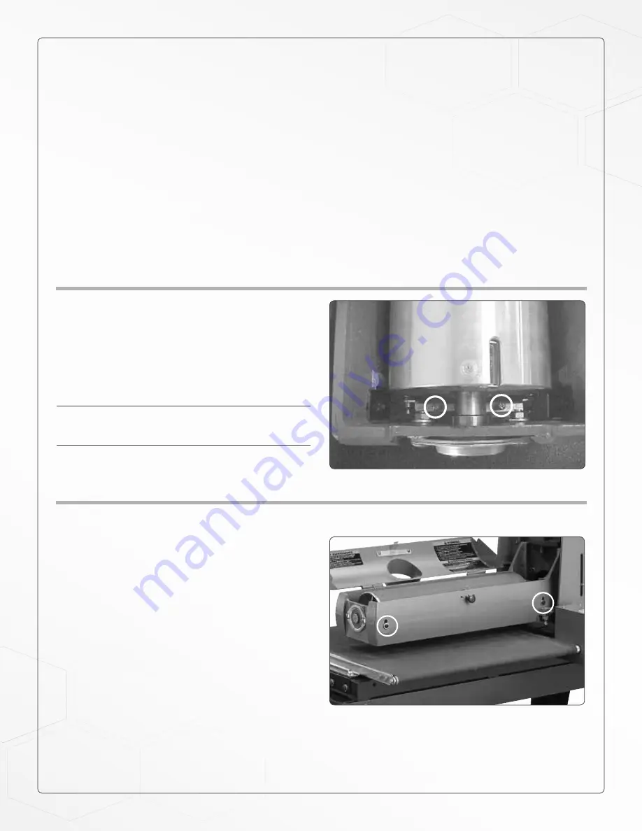
TENSION ROLLER CONTACT ADJUSTMENT
The tension rollers are factory set for the most versatile use.
1.
If necessary, to adjust tension roller contact, loosen
the four socket head screws holding the tension
roller brackets (two per side; front and back –
shown in opposite picture).
2.
Have abrasive wrapped on drum.
3.
With machine unplugged, lower sanding drum until
it rests on conveyor belt.
4.
Raise drum 2 to 3 revolutions.
5.
Tighten the four socket head screws (two per side;
front and back).
6.
Raise drum up, off of the conveyor belt.
7.
Set drum for proper sanding height and process stock.
NOTE: Too little pressure can result in slippage of stock on
conveyor belt or kick-back. Too much tension can cause
snipe when drum sanding.


