background image


14 

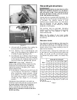
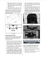
8.  Move  gauge  blocks  to  rear  drum  and 

tighten  the  other  four  hex  nuts.  Rotate  the 
rear  drum  by  hand  to  make  sure  it  lightly 
contacts  gauge  blocks  on  both  ends  after 
tightening the nuts. 

9.  Install  abrasive  strips,  close  dust  cover, 

tension the belt and reinstall the belt cover. 

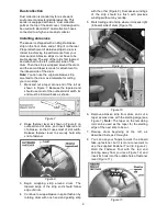
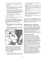
If there still is a snipe mark left on pieces being 
sanded, loosen tension roller spring retain screws 
(A, Figure 20) on both ends of rear drum and/or 
raise rear drum to keep rear drum just slightly 
lower than front drum. 


Figure 21 

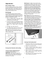
Adjusting height control 

If the height control mechanism does not operate 
smoothly or there is excessive vertical movement 
or deflection of the drum carriage, perform the 
following adjustments. 
 

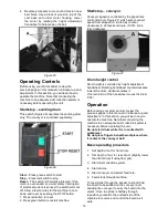
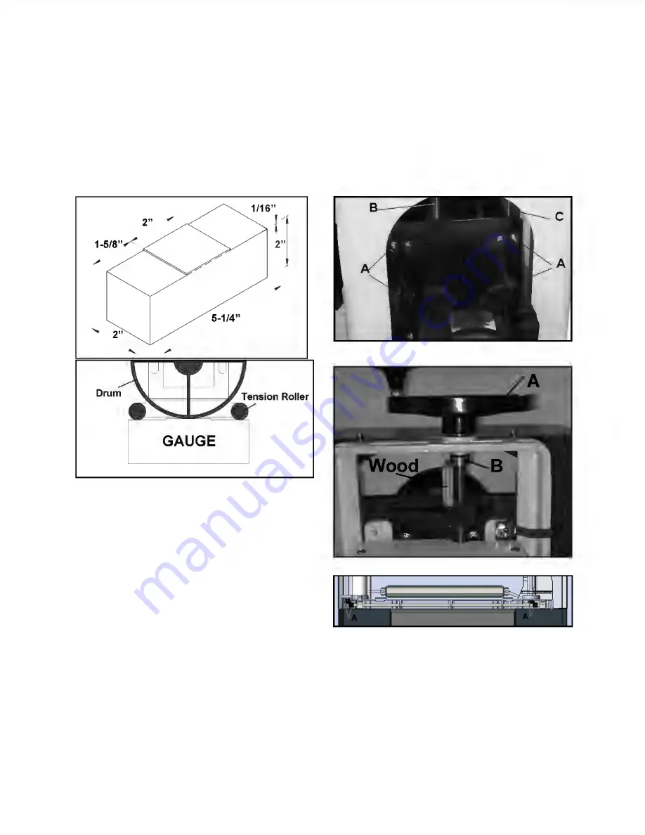
1.  Tighten  all  four  lock  nuts  (A,  Figure  22)  and 

then  loosen  them  1/8  to  1/4  turn.  If  the  lock 
nuts  are  set  too  tight,  height  control  will  not 
operate  easily.  If  the  lock  nuts  are  too  loose, 
excessive deflection or binding may occur. 

2.  Thoroughly  lubricate  the  mating  surfaces  of 

the motor mount slide (C, Figure 22), and the 
height adjustment screw (B, Figure 22). 

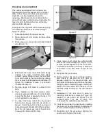
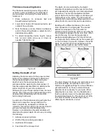
3.  Push height adjustment handwheel (A, Figure 

23)  downward  to  set  firmly  on  housing. 
Loosen  set  screws  of  shaft  collar  (B,  Figure 
23). Slide shaft collar upward against housing 
so  that  all  vertical  free  play  of  height 
adjustment screw is eliminated. Use a block of 
wood  on  top  of  the  motor  mount  plate  and 

under  collar.  Raise  the  motor  mount  plate  by 
rotating  the  handwheel  to  help  remove  free 
play.  Lubricate  around  washers  beneath 
handle and above collar. 

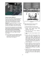
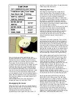
4.  If  the  height  adjustment  mechanism  still  feels 

rough,  check  the miter  gear  alignment on the 
underside  of  the  base.  The  miter  gears  (A, 
Figure 24) can be adjusted on their shafts by 
loosening the set screws on the gears. Check 
and  adjust  so  that  the  gear  mesh  is  not  too 
tight or too loose, and that the gear teeth align 
with the opposing gear. 


Figure 22 


Figure 23 


Figure 24 

Poly-v belt adjustment/ replacement 

To adjust tension or replace the poly-v belt: 

1.  Remove belt guard by removing two screws.  

2.  Loosen  the  four  cap  screws  (A,  Figure  25) 

securing motor to motor plate. 

3.  Push  down  on  motor  to  de-tension  belt,  and 

remove belt from around pulleys. 

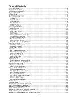
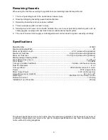
Summary of Contents for 913003

Page 1: ...r Drive Eagan Minnesota 55121 888 454 3401 Fax 651 454 3465 www supermaxtools com Operating Instructions and Parts Manual Dual Drum Sander Model 913003 Revision A 9 2012 UPERM AX TOOLS Improving Your...

Page 2: ...ocedure 15 Thickness measuring device 16 Setting the depth of cut 16 Disengaging the drums 17 Selecting feed rates 17 Edge sanding 18 Digital Readout 18 Digital readout for rear drum height 18 Digital...

Page 3: ...erred exclusively to the operator Safety General Safety Notes Woodworking machines can be dangerous if not used properly Therefore the appropriate general technical rules as well as the following note...

Page 4: ...e 28 Specifications regarding the maximum or minimum size of the work piece must be observed 29 Do not machine more than two work pieces at the same time 30 Connection and repair work on the electrica...

Page 5: ...ng Width 25 Minimum Sanding Length 2 1 4 varies with application Maximum Thickness 6 typical varies with application Minimum Thickness 1 32 typical varies with application Maximum Edge Sanding Width 6...

Page 6: ...Rear drum independently adjustable 3 Dust cover 4 Height adjustment handwheel 5 Manual scale 6 Digital readout 7 Drum motor 8 Magnetic switch 9 Conveyor gearmotor 10 Controller 11 Conveyor belt 12 Thi...

Page 7: ...on manual thoroughly for assembly maintenance and safety instructions Contents of boxes Box 1 Sander Conveyor Bed Assembly See Figure 2 1 Sander and Conveyor Bed Assembly A 2 Handle B 1 Large Handwhee...

Page 8: ...1 Remove the two shipping brackets that secured the sander to the pallet 2 Lift sander using straps beneath the cast iron frame but not directly under the drums or conveyor See Figure 5 Do not lift sa...

Page 9: ...s shown in Figure 8 on outboard end of drum and insert tapered end of abrasive so that it uses most of slot width Release fastener lever to securely hold strip end to fastener Figure 8 3 Begin wrappin...

Page 10: ...an in compliance with all relevant codes This machine must be properly grounded to help prevent electrical shock and possible fatal injury A power plug is not provided with this sander You may either...

Page 11: ...this on both sides of conveyor to obtain approximately equal tension on both sides of the belt when taut Insufficient belt tension will cause slippage of conveyor belt on the drive roller during sand...

Page 12: ...allel to the table If it is not alignment is necessary 7 To align front drum loosen the four socket head button screws A B C D as shown in Figure 17 and Figure 18 at front and rear of outboard support...

Page 13: ...ller pressure Figure 20 OR 2 Raise height of tension rollers to reduce tension roller pressure as follows 1 Disconnect sander from power source 2 Remove the belt cover and loosen the belt tension See...

Page 14: ...otor mount slide C Figure 22 and the height adjustment screw B Figure 22 3 Push height adjustment handwheel A Figure 23 downward to set firmly on housing Loosen set screws of shaft collar B Figure 23...

Page 15: ...ich sets conveyor speed from stopped 0 knob fully counter clockwise to 22 feet per minute 100 knob fully clockwise Figure 27 Drum height control Drum height is controlled by height adjustment handwhee...

Page 16: ...of cut to use including the following 1 Abrasive type and grit size 2 Width of the piece being processed 3 Hardness of the piece 4 Feed rate of the conveyor belt The depth of cut is controlled by the...

Page 17: ...he conveyor motor to maintain the highest feed rate without overload If the load on the drum motor increases the controller will decrease the conveyor feed rate and will stop the conveyor under extrem...

Page 18: ...de fence Raise rear drum until it just contacts with the workpiece but still can be rotated by hand Feeding direction is from the rear of machine to the front as the red arrows shown in Figure 34 Figu...

Page 19: ...sition as 0 5 Lower the drum with the equivalent of the distance you recorded The minus light as shown in Figure 35 will now be lit 6 Reset the position to 0 by pressing the 0 SET button again You als...

Page 20: ...s adjustments and controls will allow you to fine tune the machine for maximum results The best results come from experimenting with different abrasive grits and machine settings to match the job at h...

Page 21: ...get the best final finish however the stock should be fed through the machine so it will be sanded in line with the grain of the wood on the final one or two passes Cleaning abrasive strips Regularly...

Page 22: ...abrasive edge Abrasive strip loose 2 Strip not cut properly Recut and install abrasive strip 1 Excessive depth of cut Reduce depth of cut 2 Excessive feed rate Use slower feed rate 3 Inadequate dust c...

Page 23: ...depth of cut Reduce depth of cut or reduce feed rate Rippled sanded surface uniformly spaced ripples 3 Sander vibration Check for these conditions 1 Loose bolts or bearing and pulley set screws retigh...

Page 24: ...clean 1 Grit has been removed from backing Avoid this area of drum or change abrasive strips 1 Sensor or disc is dirty Clean sensor and disc 2 Sensor and disc misaligned Align sensor with the holes o...

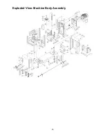
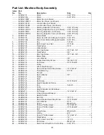
Page 25: ...25 Exploded View Machine Body Assembly...

Page 26: ...ock Washer 3 8 4 13 635DS 113 Socket Head Cap Screw 3 8 16x1 1 4 4 14 635DS 114 Set Screw 5 16 18x3 8 5 15 635DS 115 Pulley 3 16 635DS 116 Label Depth Gauge 1 17 635DS 117 Round Socket Head Cap Screw...

Page 27: ...635DS 168 Switch Plate 1 69 480BS 194 Strain Relief Switch Cord PG 11 1 70 635DS 170 Disc 1 71 635DS 171 Wave Washer 5 8 1 72 635DS 172 Sensor Drum Head Height 1 73 635DS 173 Sensor Bracket Drum Head...

Page 28: ...28 101 635DS 1101 Pointer 1 102 480BS 147 Flat Washer 5 16 9 103 480BS 199 Rotating Direction Label 1 104 635DS 1104 Grit Combinations Label 2...

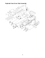
Page 29: ...29 Exploded View Drum Head Assembly...

Page 30: ...rew M5x0 8x10 4 25 635DS 225 Socket Head Cap Screw 5 16 18x1 2 2 26 635DS 226 Extension Table Bracket 1 27 480BS 171 Hex Nut w Washer M8x1 25 8 28 635DS 157 Threaded Rod 2 29 635DS 229 Key 4x4x22 2 30...

Page 31: ...DS 264 Stud 1 65 480BS 186 Hex Nut 1 4 20 1 66 635DS 266 Nylon Insert Lock Nut M5x0 8 2 67 635DS 267 Drum Carriage 1 68 635DS 268 Bearing 688ZZ 2 69 480BS 188 Flat Washer M5 2 70 635DS 270 Set Screw 1...

Page 32: ...32 Exploded View Conveyor and Motor Assembly 33 1Ph...

Page 33: ...21 635DS 321 Set Screw 5 16 18x3 8 2 22 635DS 322 Bracket Base Controller 3HP 1Ph Model 1 22A 635DS 322A Bracket Base Controller 5HP 3Ph Model 1 23 635DS 323 Cover Base Control Housing 3HP 1Ph Model...

Page 34: ...34 50 635DS 350 Lock Int Tooth Washer M5 2 51 635DS 351 Gear Motor Support Bracket 5HP 3Ph only 1 52 635DS 352 EMC Filter 1 53 480BS 213 Receptacle 3HP 1Ph only 1...

Page 35: ...ex Cap Screw 3 8 16x3 4 4 4 480BS 304 Hex Cap Screw 5 16 18x1 2 12 5 480BS 241 Flat Washer 5 16 12 6 635DS 406 Bottom Plate 1 7 635DS 407 Rear Panel 1 8 635DS 408 Front Panel 1 9 480BS 309 Door Hinge...

Page 36: ...Optional Index Part No No Description Size Qty 1 635DS 501 Base Bracket 2 2 480BS 402 Carriage Bolt 1 4 20x3 4 8 3 480BS 403 Hex Cap Screw 3 8 16x1 4 4 480BS 231 Hex Nut 1 4 20 8 5 635DS 141 Flat Wash...

Page 37: ...ALBIIARD S NSCR R AR lJU4 I D PE i GEARMOTal 230V ACTOVARI I Bl 160V DC f O IIER N UfCTRIC PANEL z CM Q I LOAD 2 LINE 2 z I LOAD 1 LIi 1 WHllE BLAa DRUM MO IOO f OIIIER 0Ull T 5 llAC im l IHnE TOIJ UM...

Page 38: ...38 Warranty 2 YEAR WARRANTY Limited warranty We will provide all replacement parts which are found to be defective in materials or workmanship Manufacturers warranties on conveyor belts...

Page 39: ...39 Notes...

Page 40: ...UST COVER OR GUARDS IN PLACE KEEP HANDS AND CLOTHING AWAYFROM OPERATING DRUM AND COUPLER ALWAYSMAINTAIN CONTROL OF STOCK TO AVOID KICKBACK KNOW HOW TO PREVENT IT ALWAYSDISCONNECT ELECTRICAL POWER BEFO...

Reviews: