18
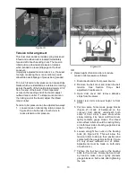
hardwoods, using a shallower depth of cut and a
faster feed rate will help minimize burn marks.
Slightly angling the stock as it is fed into the
machine may also help prevent burning the stock.
Because of the wide range of variables, it is
important to experiment with your specific
conditions and make adjustments to achieve the
optimum feed rate. If problems occur, check the
depth of cut and/or adjust the feed rate.
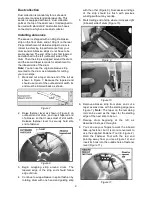
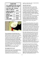
Figure 32
Edge sanding
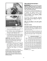
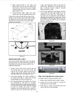
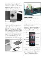
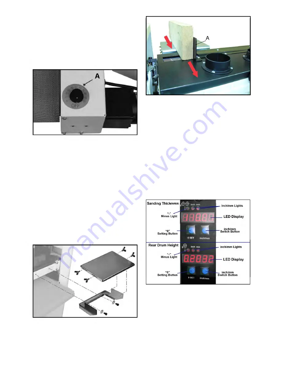
The extension table (Figure 33) is installed for
edge sanding. It can be slid in close to the dust
cover for edge sanding or slid out for opening the
dust cover.
Position the extension table level with or slightly
below the dust cover surface for proper support of
stock. To check position, place a straight edge on
top of the dust cover and extending out over the
extension table.
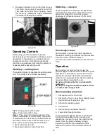
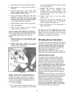
The plate (A, Figure 34) can be removed to allow
edge sanding and remounted as a vertical guide
fence. Raise rear drum until it just contacts with
the workpiece but still can be rotated by hand.
Feeding direction is from the rear of machine
to the front as the red arrows shown in Figure
34.
Figure 33
Figure 34
Digital Readout
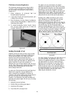
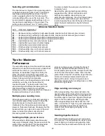
Figure 35 identifies parts of the digital readouts.
0 SET
– zero-setting
Press this button to set current position as zero
point.
inch/mm
– inch/millimeter
Pressing this button back and forth between
imperial and metric, and can be done at any time
without affecting saved settings.
The DRO comes with memory function. The LED
display will display with "-----" flash when it is
saving the setting. The setting will be kept in the
device’s memory, but it needs re-setting if you
move the drums after power off.
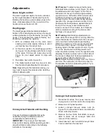
Figure 35
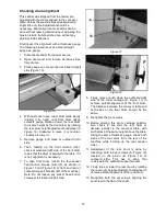
Digital readout for rear drum height
It displays the distance of the rear drum vertical
motion. It is helpful for selecting grits to use on
this dual drum machine and setting the rear drum.
There is an easy method of establishing the rear
drum to zero for this function, as follows.
1. Disconnect sander from power source.
Summary of Contents for 913003
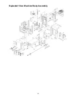
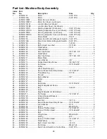
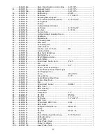
Page 25: ...25 Exploded View Machine Body Assembly...
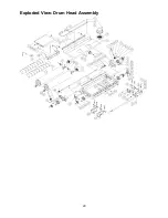
Page 29: ...29 Exploded View Drum Head Assembly...
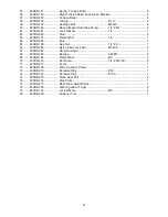
Page 32: ...32 Exploded View Conveyor and Motor Assembly 33 1Ph...
Page 39: ...39 Notes...

