

8
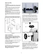
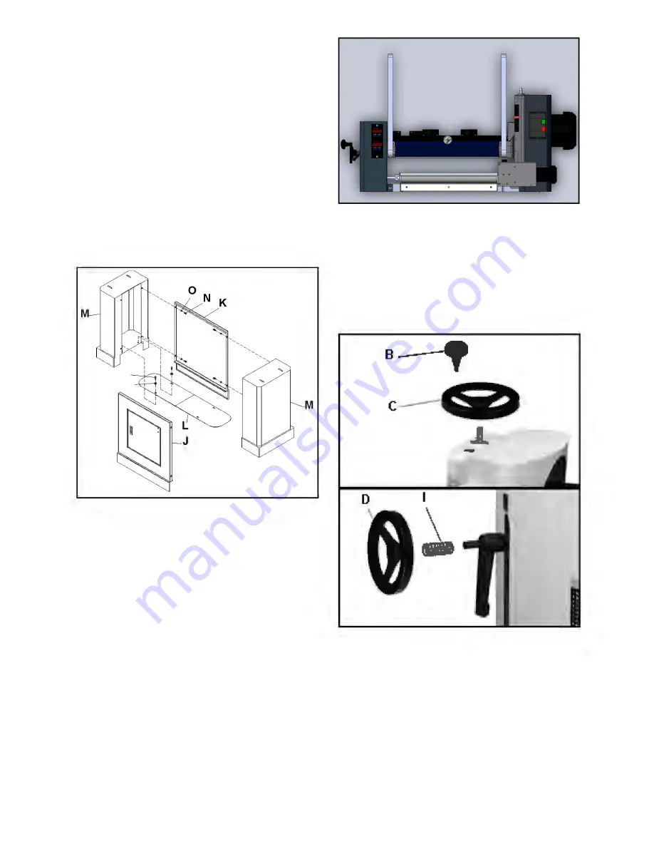
Stand assembly
See Figure 4.
1. Position two stand sides (M) on the ground with
the base down and with the openings toward the
center.
2. Mount hinged bottom plate (L) to stand sides
with four screws (N) and washers (O). Hand-
tighten only at this time.
3. Secure rear plate (K) to left and right stand
sides (M) with four screws (N) and washers (O).
Hand-tighten only.
5. Secure front plate with door (J) to left and right
stand sides (M) in same manner as above with
four screws (N) and washers (O). Hand-tighten
only.
Fasteners will be fully tightened only after sander
is mounted, to ensure proper settling of stand.
Figure 4
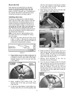
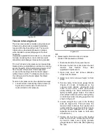
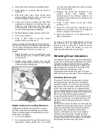
Sander installation
Sander is heavy! Exercise caution and use
properly rated lifting equipment (hoist, straps,
or forklift). Failure to comply may cause
serious injury.
1. Remove the two shipping brackets that secured
the sander to the pallet.
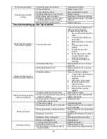
2. Lift sander using straps beneath the cast iron
frame, but not directly under the drums or
conveyor. See Figure 5
Do not lift sander under drums or conveyor
table, or any area that can be damaged or
misaligned in the process.
Figure 5
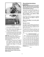
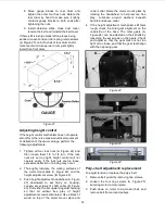
3. Position sander atop the stand. Open stand
door and secure sander from beneath using four
screws (F, Figure 2) and flat washers (G, Figure
2).
4. Attach large handwheel (C, Figure 6) to height
adjustment screw, and tighten the two set screws.
5. Install handle (B, Figure 6) into threaded hole
and tighten nut against handwheel.
Figure 6
6. Place spring (I, Figure 6) onto rear drum
adjustment shaft, and push it into recess in
locking handle. Attach small handwheel (D, Figure
6) and tighten the two set screws on the flats of
the shaft.
7. After installing sander to stand, finish tightening
all mounting hardware that was previously hand-
tightened during the stand assembly.
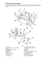
Summary of Contents for 913003
Page 25: ...25 Exploded View Machine Body Assembly...
Page 29: ...29 Exploded View Drum Head Assembly...
Page 32: ...32 Exploded View Conveyor and Motor Assembly 33 1Ph...
Page 39: ...39 Notes...


