


9
Dust collection
Dust collection is mandatory for a safe work
environment and extended abrasive life. This
sander is equipped with two 4” dust collection
ports at the top of the dust cover. It is designed to
be used with standard 4” dust collection hoses
connected to a high volume dust collector.
Installing abrasives
The sander is shipped with an 80-grit abrasive
strip on the front drum, and a 100-grit on the rear.
Proper attachment of abrasive strips to drum is
critical to achieving top performance from your
drum sander. Abrasive strips do not have to be
pre-measured. The end of the roll is first tapered
and attached to the left (outboard) side of the
drum. Then the strip is wrapped around the drum,
and the second taper is made for attachment to
the inboard side of the drum.
Note:
You can use the original abrasive strip
mounted to the drum as a template for cutting
your own strips.
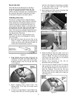
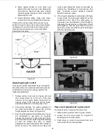
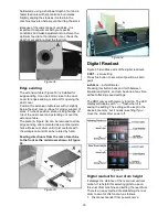
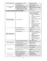
1. Mark and cut a taper at one end of the roll as
shown in Figure 7. Because the tapered end
should use most of the outboard slot width, its
end must be trimmed back as shown.
Figure 7
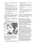
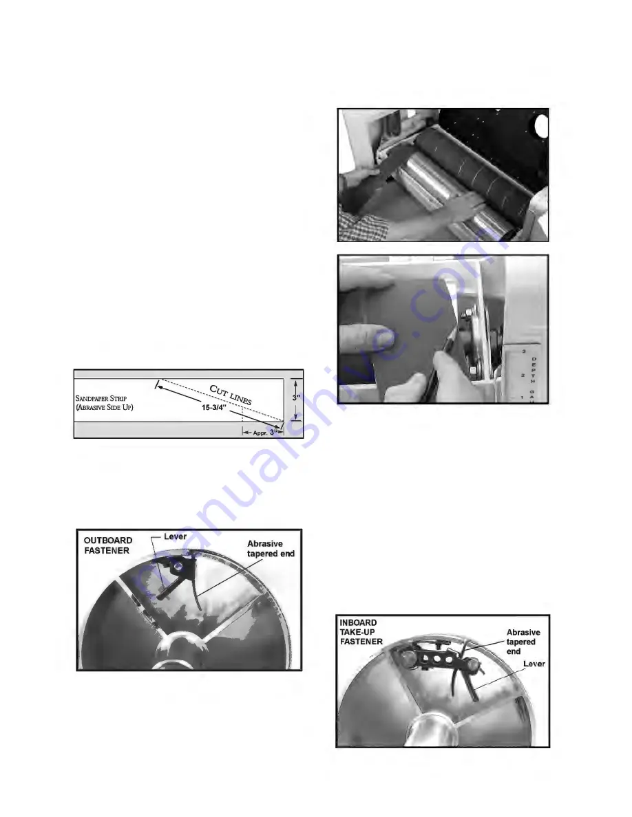
2. Raise fastener lever as shown in Figure 8 on
outboard end of drum, and insert tapered end
of abrasive so that it uses most of slot width.
Release fastener lever to securely hold strip
end to fastener.
Figure 8
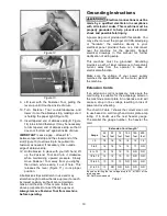
3. Begin wrapping strip around drum. The
tapered edge of the strip end should follow
edge of drum.
4. Continue to wrap abrasive in spiral fashion by
rotating drum with one hand and guiding strip
with the other (Figure 9). Successive windings
of the strip should be flush with previous
windings without any overlap.
5. Mark trailing end of strip where it crosses right
(inboard) side of drum (Figure 10).
Figure 9
Figure 10
6. Remove abrasive strip from drum, and cut a
taper as was done with the starting edge (see
Figure 7).
Note:
The taper on the remaining
roll can be used as the taper for the starting
edge of the next strip to be cut.
7. Rewrap drum beginning at the left, as
described in steps 2 through 4.
8. You can use your fingers to work the inboard
take-up fastener, but it is more convenient to
use the supplied Fastener Tool (E, Figure 2).
Hold the Fastener Tool with the red end
pointing away from you (see Figure 12) and
insert its hook into the outside hole of fastener
lever (Figure 11).
Figure 11
Summary of Contents for 913003
Page 25: ...25 Exploded View Machine Body Assembly...
Page 29: ...29 Exploded View Drum Head Assembly...
Page 32: ...32 Exploded View Conveyor and Motor Assembly 33 1Ph...
Page 39: ...39 Notes...


