background image

S

UPER

B

RUSH

S

PECIFICATIONS

27

SUPERBRUSH SPECIFICATIONS

S

UPER

B

RUSH

24           S

UPER

B

RUSH

36

Warranty: Two years on parts and labor, limited; 

Manufacturer’s warranties on conveyor belts and brush heads.

Dimensions:

Model 24: Height: 52˝  Width: 46˝; Depth: 42˝
Model 36: Height: 52˝  Width: 58˝; Depth: 42˝

Dust Hood:

Model 24: Steel hood with 4˝ vacuum port, hinged back
Model 36: Steel hood with two 4˝ vacuum ports, hinged back

Brush Speed:

Infinitely Variable, 400-1200 RPM.

Brush:

See Brushes & Supplies, page 35

Bearings:

1˝ sealed, permanently lubricated, ball.

Conveyor Bed:

Steel reinforced with four steel cross sections.

Conveyor Motor:

100 in-lbs. torque, direct-drive 

DC

motor (1/17 

HP

).

Infinitely variable from 0 to 15 feet per minute.

Conveyor Belt:

Polyurethane, roughtop surface belt, with monofilament
back, included. (Optional abrasive belt available.)

Stand

Zinc-plated steel, cast aluminum. Column tubes are 

Construction:

centerless ground.

Drive Motor:

Both Models: 5

HP

TEFC

; 1,725 

RPM

; 60 

HZ

. Continuous Duty

Single phase 208-230V; Optional three phase: 230V or (460V three phase)

Minimum Stock

All Models 10˝ without fixtures.

Length:

Height

All Models: 3/32˝ per turn; Depth Gauge with locking stop included.

Adjustment:

Stock Thickness

11˝ maximum, typical* with nylon brushes.

Capacity:

12” maximum, typical* with wire brushes.
*can vary depending on specific brush types

Approximate

Model 24: 375 lbs. 

Shipping Weight:

Model 36: 475 lbs. 

Tension Rollers:

1 1/2˝ diameter, rubber covered infeed and outfeed rollers 
mounted under spring tension, fully adjustable.

Dust Collection:

Mandatory for all models.

Summary of Contents for SUPERBRUSH 24

Page 1: ...k Reference SUPERBRUSH OWNER S MANUAL For SUPERBRUSH 24 and SUPERBRUSH 36 IMPORTANT BEFORE OPERATING YOUR SUPERBRUSH READ THE INSTRUCTIONS IN THIS MANUAL FOR UNPACKING AND SETTING UP YOUR MACHINE USA...

Page 2: ...p The main purpose in inventing and devel oping the machine you ve purchased was to bring a new dimension of productivity to your workshop be it large or small Right from the start our goal at SuperMa...

Page 3: ...OTING YOUR SUPERBRUSH Troubleshooting Guide Motors 13 Troubleshooting Guide Conveyor 14 Troubleshooting Guide Machine 15 SERVICING YOUR SUPERBRUSH Adjusting Height Controls 16 Adjusting Table Support...

Page 4: ...nveyor table 2 a brush speed control handle which controls brush speed from 400 to 1200 RPM 3 a motor starter switch which starts and stops the drive motor and sanding brush and 4 a feed rate control...

Page 5: ...loosen each set screw by first loosening its hex nut with a wrench and then the set screw with an Allen wrench Then retighten each set screw with your fingers so it only lightly touches the column tub...

Page 6: ...a 5HP three phase 208 230V motor or a 5HP three phase 460V motor Single phase motor Protected by a thermal overload switch On single phase machines a NEMA 14 30 plug is provided A 30 amp breaker is r...

Page 7: ...e placing the level on the conveyor bed If you have equipped your SUPERBRUSH with the optional caster set do the same after positioning the machine where it will be operated most often Mark the positi...

Page 8: ...et screws Position the RPM scale so that 400 RPM intersects the top of the screw support casting Fig 8 Tighten hex nuts to hold gauge in this position CHECKING THE CONVEYOR BELT Conveyor belt tracking...

Page 9: ...d select feed rate page 10 5 Start dust collector system 6 Feed stock through unit 7 Gradually increase brush speed until the desired finish is achieved Fig 8 To feed stock through the SUPERBRUSH rest...

Page 10: ...brush depth of cut used and whether the stock is fed directly in line with the conveyor bed or at an angle When using a wire brush for distressing wood a brush speed of 400 600 RPM with light contact...

Page 11: ...until the brush fibers are sharp and even DEPTH GAUGE OPERATION The depth gauge see Fig 11 measures the distance between the conveyor table and the bottom of the sanding brush The sanding brush must...

Page 12: ...Try to only process multiple pieces of similar thickness If there is a significant thickness difference the thinner pieces can slip on the conveyor belt if they do not contact the tension rollers Whe...

Page 13: ...ds 1 Inadequate circuit Check electrical requirements page 6 2 Machine overloaded Use slower feed rate slower brush RPM reduce depth of cut Conveyor 1 Motor not properly Loosen housing bolts motor osc...

Page 14: ...f cut Reduce depth of cut conveyor belt 2 Tension rollers too high Lower tension rollers page 9 3 Excessive feed rate Reduce feed rate 4 Dirty or worn conveyor Clean or replace conveyor belt belt Conv...

Page 15: ...n Retighten set screws pulley or bearing 5 Bearing worn Replace bearing page 22 Sniping of wood 1 Inadequate support Use roller stands to support stock gouging near end of stock of board 2 Conveyor dr...

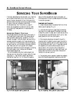
Page 16: ...ck the conveyor table for level see page 7 Then test the height adjustment mechanism See Fig 13 If it does not operate easily further adjustments may be necessary as outlined below Following these ste...

Page 17: ...and even If not adjust the gears for good mesh Measure the space between the miter gear and the adjusting screw support that holds the height adjusting screw in place Fig 15 The distance should be 1...

Page 18: ...owing checks or adjustments 1 Loosen set screws located on table support castings Fig 3 2 Lubricate thoroughly Apply penetrating lubricant to table support castings where it contacts the column tubes...

Page 19: ...nt of adjusting screw supports Fig 5 and brush support castings which could cause binding on the adjusting screw These castings can be slightly rotated by loosening the set screws which secure it to t...

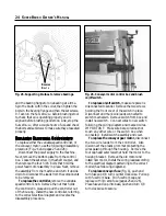
Page 20: ...ller fully inward Remove the four bolts that attach the conveyor assembly to the table mount brackets see Fig 21 Lift the conveyor and remove it from the machine by sliding the conveyor out toward the...

Page 21: ...an be lifted off the driven pulley 2 Remove the miter gear from the right inboard side of the transfer rod Fig 14 If E clips are attached to the rod remove both at this time Now loosen the shaft colla...

Page 22: ...or to its lowest position using the RPM adjustment handle Then raise motor to its highest position using the RPM adjustment han dle This loosens the V belt tension so the V belt can be lifted off the...

Page 23: ...HEAD 1 Lower motor to its lowest position using the RPM adjustment handle Then raise motor to its highest position using the RPM adjustment handle This loosens the V belt tension so the V belt can be...

Page 24: ...out of the housing Install the new controller referring to the correct electrical diagram and reverse the disassembly procedure To replace on off switch make sure power is disconnected to sander Remo...

Page 25: ...SUPERBRUSH ELECTRICAL DIAGRAM 25 SUPER BRUSH WIRING DIAGRAM 230 VOLT 1 PHASE 60 HZ...

Page 26: ...26 SUPERBRUSH OWNER S MANUAL SUPER BRUSH WIRING DIAGRAM 460 VOLT 3 PHASE 60 HZ SUPER BRUSH WIRING DIAGRAM 230 VOLT 3 PHASE 60 HZ RED WHITE NEUTRAL WHITE WHITE CONTROLLER 3 PHASE 460 V 72 1260...

Page 27: ...from 0 to 15 feet per minute Conveyor Belt Polyurethane roughtop surface belt with monofilament back included Optional abrasive belt available Stand Zinc plated steel cast aluminum Column tubes are Co...

Page 28: ...9207 8 20 WASHER 5 16 WROUGHT 11 9103 20 21 BOLT 3 8 16x1 HEX HEAD 10 9205 12 22 NUT 3 8 16 HEX 12 0005 8 23 LEVELING FOOT 20 0655 4 24 SCREW OUTBOARD HEIGHT ADJ 30 1212HR 1 25 NUT 3 8 16 FLANGE LOCK...

Page 29: ...SUPERBRUSH STAND ASSEMBLY 29...

Page 30: ...HT SUSPENSION 40 0326 2 17 BUSHING 1 2 ID OILITE ROUND 50 3107 4 18 BRACKET SUSPENSION BASE 40 0322 2 19 NUT 1 4 20 RETAINING 20 1153 4 21 ROLLER TENSION 30 1218 30 3218 2 22 NUT 5 16 18 FLANGE LOCK 1...

Page 31: ...SUPERBRUSH HEAD ASSEMBLY 31...

Page 32: ...05 1 14 V BELT 50 2029 1 15 RETAINING CLIP 72 6210 1 16 5 16 18x3 8 SOCKET HEAD SET SCREW 10 2903 1 17 CORD SET SINGLE PHASE 66 72 5315 1 CORD SET THREE PHASE 66 72 5305 1 18 KEY STOCK 1 4x1 3 4 N A 1...

Page 33: ...SUPERBRUSH CONVEYOR MOTOR ASSEMBLY 33...

Page 34: ...IL 40 4105 1 42 ROLLER SUPPORT BRACKET 40 4109 1 43 3 8 16x3 4 CARRIAGE BOLT 10 1301 4 44 3 8 16x1 CARRIAGE BOLT 10 1302 16 45 5 16 24 FLANGE NUT 12 0308 6 46 5 15 24x3 STUD 30 1306 2 47 TAKE UP BASE...

Page 35: ...contact Performax Products Inc for a complete listing of brushes and brush material available or to run test samples of your specific application SUPPLIES ITEM DESCRIPTION QTY 98 0130 Caster Set Heavy...

Page 36: ...UPERBRUSH WITHOUT ITS DUST COVER OR PULLEYGUARD IN PLACE KEEP HANDS AND CLOTHING AWAY FROM OPERATING BRUSH BELT AND PULLEYS ALWAYS MAINTAIN CONTROL OF STOCK TO AVOID KICKBACK KNOW HOW TO PREVENT IT AL...

Reviews: