46
SuperStorage Server 6039P-E1CR16H/L User's Manual
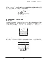
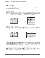
Trusted Platform Module Header
Pin Definitions
Pin#
Definition
Pin#
Definition
1
+3.3V
2
SPI_CS#
3
RESET#
4
SPI_MISO
5
SPI_CLK
6
GND
7
SPI_MOSI
8
9
+3.3V Stdby
10
SPI_IRQ#
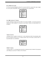
TPM/Port 80 Header
A Trusted Platform Module (TPM)/Port 80 header is located at JTPM1 to provide TPM support
and Port 80 connection. Use this header to enhance system performance and data security.
Refer to the table below for pin definitions. The following document provides information about
the TPM:
http://www.supermicro.com/manuals/other/TPM.pdf
.
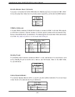
Standby Power
The Standby Power header is located at JSTBY1 on the motherboard. You must have a card
with a Standby Power connector and a cable to use this feature. Refer to the table below
for pin definitions.
Standby Power
Pin Definitions
Pin#
Definition
1
+5V Standby
2
Ground
3
No Connection
Internal Speaker/Buzzer
The Internal Speaker/Buzzer (SP1) is used to provide audible indications for various beep
codes. Refer to the table below for pin definitions.
Internal Buzzer
Pin Definitions
Pin#
Definition
1
Pos (+)
Beep In
2
Neg (-)
Alarm Speaker
Disk-On-Module Power Connector
Two power connectors for SATA DOM (Disk-On-Module) devices are located at JSD1/JSD2.
Connect appropriate cables here to provide power support for your Serial Link DOM devices.
DOM Power
Pin Definitions
Pin#
Definition
1
5V
2
Ground
3
Ground

