48
SuperStorage Server 6039P-E1CR16H/L User's Manual
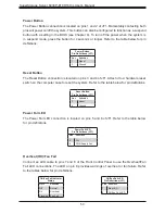
Power LED/Speaker
Pins 1-3 of JD1 are used for power LED indication, and pins 4-7 are for the speaker. The
speaker connector pins (4-7) are used with an external speaker. If you wish to use the onboard
speaker, close pins 6-7 with a cap. Refer to the tables below for pin definitions.
PWR LED Connector
Pin Definitions
Pin#
Signal
1
JD1_PIN1
2
FP_PWR_LED
3
FP_PWR_LED
Speaker Connector
Pin Definitions
Pin#
Signal
4
P5V
5
Key
6
R_SPKPIN_N
7
R_SPKPIN
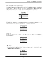
Overheat/Fan Fail LED Header
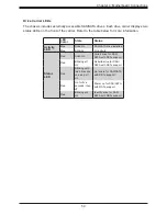
The JOH1 header is used to connect an LED indicator to provide warnings of chassis
overheating and fan failure. This LED blinks when a fan failure occurs. Refer to the tables
below for pin definitions.
Overheat LED header
Status
State
Definition
Solid
Overheat
Blinking Fan Fail
Overheat LED
Pin Definitions
Pin#
Signal
1
Pull high to +3.3V
power through 330-ohm
resistor
2
OH Active
SATA and SAS Ports
The X11DPH-T has eight SATA 3.0 ports (I-SATA0~3, I-SATA4~7) supported by the Intel C624
chipset. These SATA ports support RAID 0, 1, 5, and 10. There are also two S-SATA ports
(S-SATA0, S-SATA1) that include SATA DOM power. SATA ports provide serial-link signal
connections, which are faster than the connections of Parallel ATA. In addition, the X11DPH-T
has eight SAS 3.0 ports (L-SAS0~7) that are supported by the LSI 3008 controller.
Note
: For more information on the SATA HostRAID configuration, please refer to the Intel
SATA HostRAID user's guide posted on our website at
http://www.supermicro.com.
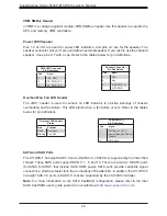
VRM SMBus Header
JVRM1 is a voltage regulator module (VRM) SMBus header. Use this header to program the
CPU and memory VRM controllers.

