49
Chapter 4: Motherboard Connections
NVMe Slots
Two NVM Express slots are located at JNVME1 and JNVME2 on the motherboard. Use these
slots to attach high-speed PCI-E storage devices.
Intel RAID Key Header
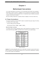
The JRK1 header allows the user to enable RAID functions. Refer to the table below for pin
definitions.
Overheat LED
Pin Definitions
Pin#
Defintion
1
GND
2
PU 3.3V Stdby
3
GND
4
PCH RAID KEY
Figure 4-1. JF1: Control Panel Pins
Control Panel
JF1 contains header pins for various control panel connections. Refer to the figure below for
the pin locations and definitions of the control panel buttons and LED indicators.
All JF1 wires have been bundled into a single cable to simplify this connection. Verify that
the red wire plugs into pin 1 as marked on the motherboard. The other end connects to the
control panel PCB board.
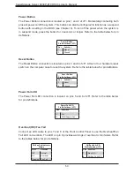
Power Button
UID LED
NIC1 Active LED
Reset Button
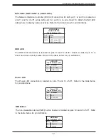
HDD LED
PWR LED
Reset
PWR
3.3V Stby
3.3V Stby
19
X
Ground
X
3.3V Stby
20
1
2
Ground
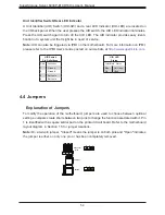
NIC2 Active LED
NMI
3.3V
3.3V
Power Fail LED
OH/Fan Fail LED
Ground

