AOC-SLG3-2E4R Expansion Card User's Guide
2-4
+
+
3
2
1
4
3
2
1
4
1
2
3
3
2
1
1
3
1
3
1
3
18
19
27
28
45
46
54
18 19
27
28
45
46
54
A1
A2
A7
A8
CG
1
CG
2
B1
B2
B7
B8
C1
C2
C7
C8
D1
D2
D7
D8
CG
3
E1
E2
G2
F2
F1
H2
H1
G1
F7
F8
G8
E7
G7
H7
H8
E8
PRESS FIT
DESIGNED IN USA
BAR CODE
AOC-SL
G3-2E4R
RE
V:
1.00
C2
C1
J1
JNVI2C
U7
U6
U4
U3
U1
U32
U5
JP3
JP2
JP1
MH1
MH2
U33
U28
U29
J2
NVM
e1
NVM
e0
2-3:FRU SMBus ADDR A2=1
1-2:FRU SMBus ADDR A2=0
1-2:FRU SMBus ADDR A1=0
2-3:FRU SMBus ADDR A1=1
JP2:
1-2:FRU SMBus ADDR A0=0
JP1:
2-3:FRU SMBus ADDR A0=1
JP3:
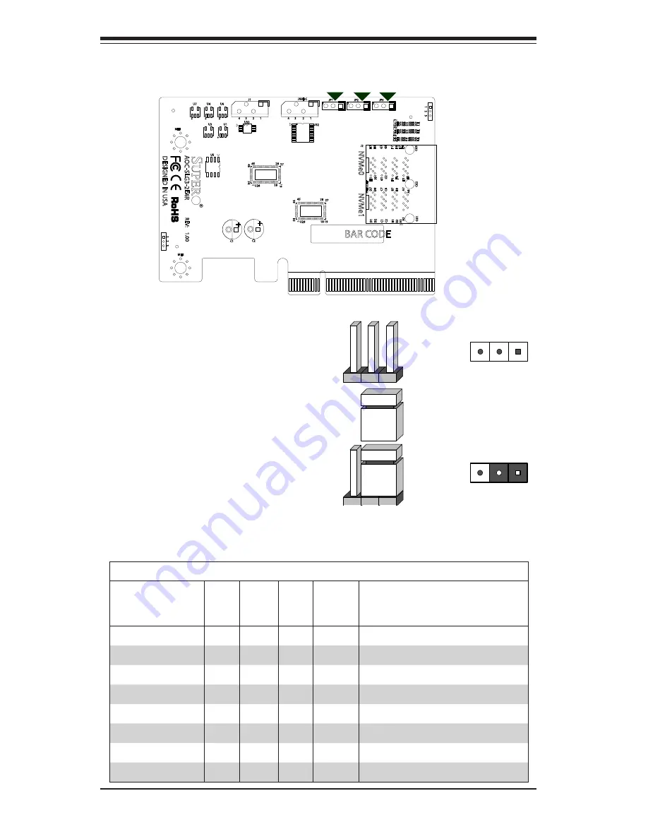
2-4 Front Jumper Location and Settings
Explanation of Jumpers
To modify the operation of the backplane,
jumpers can be used to choose between
optional settings. Jumpers create shorts
between two pins to change the function
of the connector. Pin 1 is identified with
a square solder pad on the printed circuit
board. Note: On two pin jumpers, "Closed"
means the jumper is on and "Open" means
the jumper is off the pins.
Connector
Pins
Jumper
Setting
3 2 1
3 2 1
JP1 JP2 JP3
Figure 2-4. Front Jumpers
Table of Addresses Based on Jumper Settings
MSN
JP3
A2
JP2
A1
JP1
A0
LSB
Hex Address
1010
0
0
0
0
A 0
1010
0
0
1
0
A 2
1010
0
1
0
0
A 4
1010
0
1
1
0
A 6
1010
1
0
0
0
A 8
1010
1
0
1
0
A A
1010
1
1
0
0
A C
1010
1
1
1
0
A E
Note: Unless explicitly instructed otherwise by the manufacturer, do not move the
jumpers from their default locations of pins 1-2. Doing so will likely cause the card
to become disabled.


