10
Supermicro SC116B Chassis Series User's Manual
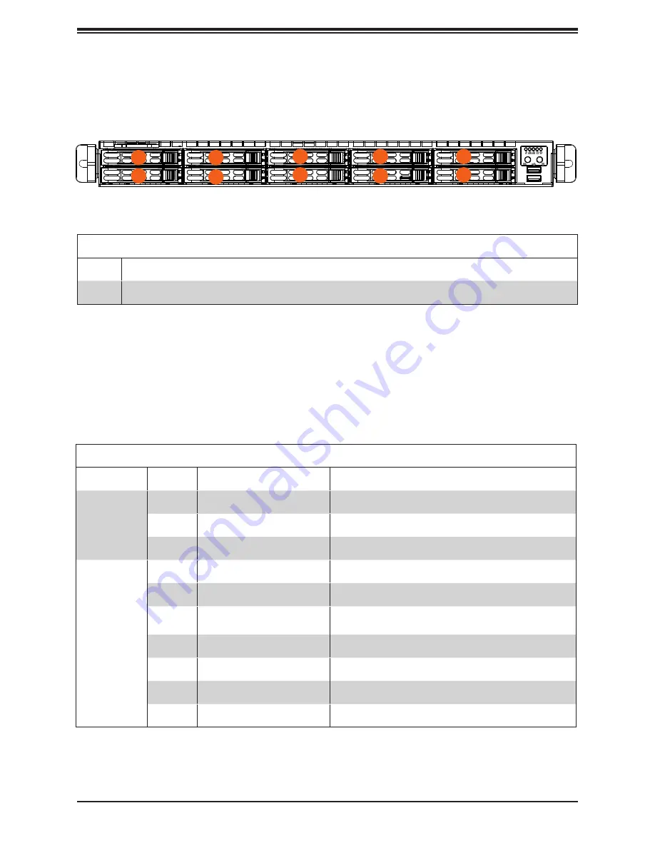
Figure 1-2. Chassis Front View
Logical Storage Drive Numbers
Item
Description
0-9
Ten 2.5" front drive bays (SAS*/SATA)
* SAS support available with additional parts.
Chassis Front
The illustration below shows the features included on the front of the chassis.
Drive Carrier Indicators
Each drive carrier has two LED indicators: an activity indicator and a status indicator. For
RAID configurations using a controller, the meaning of the status indicator is described in
the table below. For OS RAID or non-RAID configurations, some LED indications are not
supported, such as hot spare.
Drive Carrier LED Indicators
Color
Blinking Pattern
Meaning
Activity LED
Blue
Solid On
Idle SAS/NVMe drive installed
Blue
Blinking
I/O activity
Off
Idle SATA drive installed
Status LED
Red
Solid On
Failure of drive with RSTe support
Red
Blinking at 1 Hz
Rebuild drive with RSTe support
Red
Blinking with two blinks and
one stop at 1 Hz
Hot spare for drive with RSTe support
Red
On for five seconds, then off
Power on for drive with RSTe support
Red
Blinking at 4 Hz
Identify drive with RSTe support
Green
Solid on
Safe to remove NVMe drive
Amber
Blinking at 1Hz
Do not remove NVMe drive
1
4
3
2
0
5
6
7
8
9


