background image

2-1

Chapter 2: Warning Statements for AC Systems

Chapter 2  


Standardized Warning Statements for AC Systems


About Standardized Warning Statements

The following statements are industry standard warnings, provided to warn the user 
of situations which have the potential for bodily injury. Should you have questions 
or experience difficulty, contact Supermicro's Technical Support department 

for  assistance.  Only  certified  technicians  should  attempt  to  install  or  configure 

components. 

Read this appendix in its entirety before installing or configuring components in the 

Supermicro chassis.
These warnings may also be found on our web site at http://www.supermicro.com/
about/policies/safety_information.cfm.

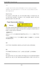
Warning!

This warning symbol means danger. You are in a situation that could cause bodily 
injury. Before you work on any equipment, be aware of the hazards involved with 
electrical circuitry and be familiar with standard practices for preventing accidents. 

Warning Definition

警告の定義

この警告サインは危険を意味します。

人身事故につながる可能性がありますので、いずれの機器でも動作させる前に、
電気回路に含まれる危険性に

注意して、標準的な事故防止策に精通して下さい。

此警告符号代表危险。

您正处于可能受到严重伤害的工作环境中。在您使用设备开始工作之前,必须充分意
识到触电的危险,并熟练掌握防止事故发生的标准工作程序。请根据每项警告结尾的
声明号码找到此设备的安全性警告说明的翻译文本。

此警告符號代表危險。

您正處於可能身體可能會受損傷的工作環境中。在您使用任何設備之前,請注意觸電
的危險,並且要熟悉預防事故發生的標準工作程序。請依照每一注意事項後的號碼找
到相關的翻譯說明內容。

Summary of Contents for CSE-846BE1C-R609JBOD

Page 1: ...USER S MANUAL Revision 1 0a SC846B JBOD Storage Enclosure Series CSE 846BE1C R609JBOD CSE 846BE2C R609JBOD...

Page 2: ...all claims will not exceed the price paid for the hardware product FCC Statement This equipment has been tested and found to comply with the limits for a Class A or Class B digital device pursuant to...

Page 3: ...ailable when this document was published Refer to the Supermicro web site for updates on supported parts and configurations This manual may be periodically updated without notice Please check the Supe...

Page 4: ...ut Standardized Warning Statements 2 1 Warning Definition 2 1 Installation Instructions 2 4 Circuit Breaker 2 5 Power Disconnection Warning 2 6 Equipment Installation 2 8 Restricted Area 2 9 Battery H...

Page 5: ...orage 4 5 4 4 Removing the Chassis Cover 4 7 4 5 Installing Hard Drives 4 8 4 6 System Fans 4 11 4 7 Power Supply 4 13 4 8 Control Board 4 15 4 9 Accessing the Backplane 4 16 Chapter 5 Rack Installati...

Page 6: ...ines 6 1 General Safety Guidelines 6 2 6 3 Components Connectors Jumpers and LEDs 6 2 Component and Connector Definitions 6 3 Jumpers and LED Indicators 6 4 6 4 I2 C Cabling to the Backplane 6 6 6 5 J...

Page 7: ...e chassis is equipped with a redundant efficient power supply for outstanding power savings with specially designed optimized cooling Quick release tool less slide rails are available for quick instal...

Page 8: ...rs Control Board The JBOD control board allows the user to remotely control and monitor the chassis resources using the BMC such as powering on or off controlling fan speeds and reading temperature da...

Page 9: ...must be mailed when service is complete For faster service RMA authorizations may be requested online http www supermicro com support rma Whenever possible repack the chassis in the original Supermicr...

Page 10: ...ope Address Super Micro Computer B V Het Sterrenbeeld 28 5215 ML s Hertogenbosch The Netherlands Tel 31 0 73 6400390 Fax 31 0 73 6416525 Email sales supermicro nl General Information support supermicr...

Page 11: ...for assistance Only certified technicians should attempt to install or configure components Read this appendix in its entirety before installing or configuring components in the Supermicro chassis Th...

Page 12: ...dere los riesgos de la corriente el ctrica y familiar cese con los procedimientos est ndar de prevenci n de accidentes Al final de cada advertencia encontrar el n mero que le ayudar a encontrar el tex...

Page 13: ...k letsel kan veroorzaken Voordat u aan enige apparatuur gaat werken dient u zich bewust te zijn van de bij een elektrische installatie betrokken risico s en dient u op de hoogte te zijn van de standaa...

Page 14: ...des Systems an die Stromquelle die Installationsanweisungen lesen Advertencia Lea las instrucciones de instalaci n antes de conectar el sistema a la red de alimentaci n Attention Avant de brancher le...

Page 15: ...ert ist Stellen Sie sicher dass der Nennwert der Schutzvorrichtung nicht mehr als 250 V 20 A betr gt Advertencia Este equipo utiliza el sistema de protecci n contra cortocircuitos o sobrecorrientes de...

Page 16: ...vor es Warning The system must be disconnected from all sources of power and the power cord removed from the power supply module s before accessing the chassis interior to install or remove system com...

Page 17: ...r del chasis para instalar o para quitar componentes de sistema Attention Le syst me doit tre d branch de toutes les sources de puissance ainsi que de son cordon d alimentation secteur avant d acc der...

Page 18: ...Das Installieren Ersetzen oder Bedienen dieser Ausr stung sollte nur geschultem qualifiziertem Personal gestattet werden Advertencia Solamente el personal calificado debe instalar reemplazar o utiliz...

Page 19: ...stallation in Bereichen mit beschr nktem Zutritt vorgesehen Der Zutritt zu derartigen Bereichen ist nur mit einem Spezialwerkzeug Schloss und Schl ssel oder einer sonstigen Sicherheitsvorkehrung m gli...

Page 20: ...equivalent type recommended by the manufacturer Dispose of used batteries according to the manufacturer s instructions Waarschuwing Dit apparaat is bedoeld voor installatie in gebieden met een beperk...

Page 21: ...ecommand e par le fabricant Jeter les piles usag es conform ment aux instructions du fabricant Advertencia Existe peligro de explosi n si la bater a se reemplaza de manera incorrecta Reemplazar la bat...

Page 22: ...fuentes de alimentaci n Para cortar por completo el suministro de energ a deben desconectarse todas las conexiones Attention Cette unit peut avoir plus d une connexion d alimentation Pour supprimer to...

Page 23: ...ero es peligroso Tenga cuidado cuando lo revise Attention Lorsque le syst me est en fonctionnement des tensions lectriques circulent sur le fond de panier Prendre des pr cautions lors de la maintenanc...

Page 24: ...cal codes Warnung Die Installation der Ger te muss den Sicherheitsstandards entsprechen Advertencia La instalacion del equipo debe cumplir con las normas de electricidad locales y nacionales Backplane...

Page 25: ...ional laws and regulations Attention L quipement doit tre install conform ment aux normes lectriques nationales et locales Waarschuwing Bij installatie van de apparatuur moet worden voldaan aan de lok...

Page 26: ...tos nacionales Attention La mise au rebut ou le recyclage de ce produit sont g n ralement soumis des lois et ou directives de respect de l environnement Renseignez vous aupr s de l organisme comp tent...

Page 27: ...dedos los destornilladores y todos los objetos lejos de las aberturas del ventilador Attention Il est possible que les ventilateurs soient toujours en rotation lorsque vous retirerez le bloc ventilat...

Page 28: ...r kann zu einer Fehlfunktion oder ein Brand entstehen Elektrische Ger te und Material Safety Law verbietet die Verwendung von UL oder CSA zertifizierte Kabel UL oder CSA auf der Code f r alle anderen...

Page 29: ...utres appareils lectriques que les produits d sign s par Supermicro seulement AC AC UL CSA UL CSA UL CSA Supermicro UL CSA AC Electrical Appliance and Material Safety Law UL CSA UL CSA Waarschuwing Bi...

Page 30: ...2 20 SC846B JBOD Chassis Manual Notes...

Page 31: ...The server includes a control panel on the front that houses power buttons and status monitoring lights The externally accessible hard drives display status lights The power supply displays status lig...

Page 32: ...Panel Buttons The chassis includes two push buttons that control power to the system Power Indicates power is being supplied to the system power supply units This LED is illuminated when the system i...

Page 33: ...se this function to locate the server in a rack mount environment Blinking blue Remote UID is on Use this function to identify the server from a remote location Power Fail Indicates a power supply mod...

Page 34: ...lure Red Blinking RAID activity When the red LED is blinking it indicates that the system is either building initializing or rebuilding RAID 3 5 Power Supply LEDs On the rear of the power supply modul...

Page 35: ...n the chassis The only tool required is a Phillips screwdriver Review the warnings and precautions listed in the manual before setting up or servicing this chassis These include information in Chapter...

Page 36: ...tes the power up sequence in three seconds After Normal Shutdown by BMC or Power Button Press the power button once The JBOD control board will initiate the power up sequence in three seconds After a...

Page 37: ...r Figure 4 2 For more information on the BMC see Section 6 6 in this manual Removing Power from the System Before performing most setup or maintenance tasks use the following procedure to ensure that...

Page 38: ...ry receptacles marked In If using the E2C model CSE 846BE2C R609JBOD for redundancy connect two more mini SAS HD cables to the top two Secondary receptacles also marked In Cables are described in Appe...

Page 39: ...ge Single HBA Cascading Storage The following diagram shows a server with a single host bus adapter HBA and requires only the primary expander on the backplane The SC846B JBOD storage enclosure model...

Page 40: ...The following diagram shows a server with dual HBAs and requires the primary and secondary expanders on the backplane The SC846B JBOD storage enclosure model E2C accommodates this configuration Server...

Page 41: ...he back of the power supplies 2 Press the release tabs to remove the cover from the locked position Press both tabs at the same time 3 Once the top cover is released from the locked position slide the...

Page 42: ...ion Except for short periods of time such as swapping hard drives do not operate the server with the hard drive bays empty Removing Hard Drive Carriers from the Chassis 1 Press the release button on t...

Page 43: ...Remove the two screws securing the dummy drive to the drive carrier and remove the dummy drive 2 Slide the hard drive into the carrier with the printed circuit board side facing down Figure 4 6 Removi...

Page 44: ...Secure the hard drive to the carrier using six screws 5 Replace the drive carrier into the chassis Make sure to close the drive carrier handle to lock the drive carrier into place Drive Carrier SAS SA...

Page 45: ...run the server for an extended time with the chassis open 2 Remove the failed fan s power cord from the JBOD control board 3 Press the fan release tab to lift the failed fan from the chassis and pull...

Page 46: ...SC846B JBOD Chassis Manual 4 12 Figure 4 11 Placing a Mid chassis Fan...

Page 47: ...plies are auto switching capable This feature enables them to automatically sense the input voltage and operate at a 100 120v or 180 240v An amber light will be illuminated on the power supply when th...

Page 48: ...er supply out using the handle provided 4 Replace the failed power module with another of the same model 5 Push the new power supply module into the power bay until it clicks into the locked position...

Page 49: ...board CSE PTJBOD CB3 allows the user to remotely control and monitor the chassis resources using the BMC such as powering on or off controlling fan speeds and reading temperature data from the backpla...

Page 50: ...1 Power down the system remove the power cords from the back of the power supplies and remove the chassis cover 2 Disconnect the cabling to the backplane 3 On the right side of the chassis remove the...

Page 51: ...lane housing to the chassis floor and set these aside for later use 6 Gently ease the backplane up and out of the chassis Figure 4 15 Removing the Lower Backplane Housing Screws Figure 4 16 Removing t...

Page 52: ...s housing back into position in the chassis 2 Install the five lower screws which secure the backplane housing to the chassis floor Slide the Backplane into the Chassis Install the Five Lower Screws F...

Page 53: ...er Screws Figure 4 19 Installing the Upper Screws 3 3 Install the four upper screws which secure the backplane housing to the chassis 4 Install the two screws on the right side of the chassis to secur...

Page 54: ...SC846B JBOD Chassis Manual 4 20 Notes...

Page 55: ...Avoid areas where heat electrical noise and electromagnetic fields are generated A nearby grounded power outlet is required The box your chassis was shipped in should include two sets of rail assembli...

Page 56: ...overextended Have a rack lift in place as a precaution in case the test fails In any instance of pulling the system from the rack always use a rack lift and follow all associated safety precautions Ge...

Page 57: ...sideration of equipment nameplate ratings should be used when addressing this concern Reliable Ground A reliable ground must be maintained at all times To ensure this the rack itself should be grounde...

Page 58: ...tly to the chassis an outer rail that secures to the rack and a middle rail which extends from the outer rail These assemblies are specifically designed for the left and right side of the chassis and...

Page 59: ...from coming completely out of the rack when when the chassis is pulled out for servicing To mount the rail onto the chassis first release the inner rail from the outer rails 1 Pull the inner rail out...

Page 60: ...g the hooks of the chassis with the inner rail holes Make sure the rail faces outward so that it will fit with the rack s mounting bracket 2 Slide the rail toward the front of the chassis to hook the...

Page 61: ...5 7 Chapter 5 Rack Intallation 1 1 1 2 1 3 Warning Do not pick up the server by the front handles They are designed to pull the system from a rack only...

Page 62: ...rails to the rack 4 Pull out the rear of the outer rail adjusting the length until it just fits within the posts of the rack 5 Hang the hooks of the rear section of the outer rail onto the square hole...

Page 63: ...even on both both sides You may have to depress the locking tabs while inserting When the server has been pushed completely into the rack the locking tabs should click into the locked position 3 If s...

Page 64: ...avy chassis from the rack without assistance Be sure to have sufficient assistance supporting the chassis when removing it from the rack Use a lift Removing the Chassis from the Rack 1 Pull the chassi...

Page 65: ...permicro web site at www supermicro com for the latest updates compatible parts and supported configurations 6 2 Safety Guidelines ESD Safety Guidelines Electrostatic Discharge ESD can damage electron...

Page 66: ...5 6 1 3 1 3 3 2 1 4 3 2 1 4 3 2 1 4 3 2 1 4 24 13 12 1 A 1 E 3 K 7 9 R 3 2 1 1 2 3 1 2 7 8 1 2 7 8 1 2 7 8 1 2 7 8 1 2 19 20 1 5 1 5 6 9 1 2 10 4 1 4 1 4 1 4 1 4 1 4 1 4 1 4 1 4 1 4 1 1 7 6 12 15 17...

Page 67: ...he chassis using cable CBL NTWK 0584 or CBL NTWK 0587 8 Control Panel Connector This connector is designated JF1 and connects to the control panel on the chassis See Chapter 3 for additional control p...

Page 68: ...To enable SAS2 or SAS3 functionality on the I2 C connectors set the JP5 jumper as noted 1 2 5 6 1 3 1 3 3 2 1 4 3 2 1 4 3 2 1 4 3 2 1 4 24 13 12 1 A 1 E 3 K 7 9 R 3 2 1 1 2 3 1 2 7 8 1 2 7 8 1 2 7 8...

Page 69: ...1 4 1 4 1 4 1 4 1 4 1 4 1 4 1 4 1 1 7 6 12 15 17 13 14 16 19 18 A C A C A E K R Y 1 5 10 20 12 13 24 25 36 37 48 MH2 MH4 JP6 U U18 U17 U16 U14 U13 JP7 JP5 JP1 JP2 JP3 JP4 JPW1 BT1 C10 Y2 U9 MH3 MH1 C...

Page 70: ...U16 U14 U13 JP7 JP5 JP1 JP2 JP3 JP4 JPW1 BT1 C10 C146 Y2 U9 MH3 MH1 J4 J6 J7 J5 U10 JF1 Q19 Q18 Q13 JPI2C1 J3 J2 U12 U11 C8 C9 FAN1 FAN2 FAN3 FAN4 FAN5 FAN6 FAN7 FAN8 FAN10 FAN9 J8 U8 Q3 Q16 R138 C14...

Page 71: ...initiates the power up sequence in three seconds After Normal Shutdown by BMC or Power Button Press the power button once The JBOD control board will initiate the power up sequence in three seconds Af...

Page 72: ...d The sticker also displays the BMC MAC address Figure 6 5 BMC Password Label IP Address The default IP address configuration mode is Dynamic Host and Configuration Protocol DHCP When connected to the...

Page 73: ...of finding the IP address 1 Identify the JBOD enclosure name for example dev sg4 2 Use the vpd command to view the IP address root hdmaster user sg_vpd p 0x85 dev sg4 Management network addresses VPD...

Page 74: ...6 10 SC846B JBOD Chassis Manual Notes...

Page 75: ...OD Power Supply Specifications This appendix lists power supply specifications for your chassis system 650W Redundant Supermicro Part PWS 609P 1R2 with PDB AC Input 100 240 V 4 5 11 Amp 50 60 Hz DC Ou...

Page 76: ...SC846B JBOD Chassis Manual A 2...

Page 77: ...quipment from ESD Use a grounded wrist strap designed to prevent static discharge Touch a grounded metal object before removing a component from the antistatic bag Handle the backplane by its edges on...

Page 78: ...igh quality performance This manual reflects BPN SAS3 846EL Revision 1 01 the most current release available at the time of publication All images and layouts shown in this guide are based upon the la...

Page 79: ...122 C354 C76 U35 J52 J51 J49 J50 MH15 MH13 MH14 MH27 MH26 MH25 MH24 MH23 MH22 MH21 MH20 MH19 MH18 MH17 MH16 ACTLED HS2 HS1 J30 JP3 J31 JP4 J24 J29 U51 Q873 Q866 Q872 Q871 Q868 Q867 Q870 Q869 U25 U20 U...

Page 80: ...provide power to the backplane See the table on the right for pin definitions 4 5 Primary and Secondary SAS Ports TheprimarySASconnectorsaredesignated J49 and J50 The secondary SAS Ports are designate...

Page 81: ...7 F73 BC57 BC29 C165 C107 BC10 BC96 L3 C308 C177 C122 C354 C76 U35 J52 J51 J49 J50 MH15 MH13 MH14 MH27 MH26 MH25 MH24 MH23 MH22 MH21 MH20 MH19 MH18 MH17 MH16 ACTLED HS2 HS1 J30 JP3 J31 JP4 J24 J29 U51...

Page 82: ...G7 H7 H8 E8 PRESS FIT CG5 CG2 BPN SAS3 846EL2 REV 1 01 DESIGNED IN USA 1 1 4 1 4 1 4 1 4 1 4 1 4 14 6 7 8 13 2 6 7 8 9 13 11 12 22 11 12 22 11 11 12 22 11 12 22 11 12 22 12 13 14 23 2 11 12 13 14 23...

Page 83: ...A C A C A C A C A C A C A C A C C A C A C A C A C A C A C A C A C A C A C A C A C A CA C A C A C A C A C A C A C A C A C A C A C A C A C A C A C A C A C A C A C A C A C A C A C A C A C P15 P15 U44 U36...

Page 84: ...D Chassis Manual Front SAS SATA Connectors and LED Indicators Drive Number Label HDD Activity LED blue Failure LED red SAS 20 J20 ACT20 FAIL20 SAS 21 J21 ACT21 FAIL21 SAS 22 J22 ACT22 FAIL22 SAS 23 J2...

Page 85: ...R6 R65 TP95 TP94 TP15 TP36 C128 C135 C233 C236 C206 C24 CS21 CT199 12V_LED2 5V_LED2 5V_LED1 12V_LED1 OVERHEATFAIL1 LED Testing Only P_UART P_MDIO P_SDB S_MDIO S_SDB S_UART EXP I2C0 EXP I2C4 5V GND 12V...

Page 86: ...P95 TP94 TP15 TP36 C128 C135 C233 C236 C206 C24 CS21 CT199 12V_LED2 5V_LED2 5V_LED1 12V_LED1 OVERHEATFAIL1 LED Testing Only P_UART P_MDIO P_SDB S_MDIO S_SDB S_UART EXP I2C0 EXP I2C4 5V GND 12V 5V GND...

Page 87: ...SAST 0507 01 Length 80 cm 31 inches Description This cable has an iPass SFF 8087 Mini SAS connector 36 pin at one end and a Mini SAS HD SFF 8643 connector at the other end It connects from the SAS2 HB...

Page 88: ...host bus configuration the backplane connects to one host bus adapter Single Host Bus Adapter Failover If the expander or data path in Port A fails the system automatically switches to Port B with ap...

Page 89: ...IT CG5 CG2 A1 A2 A7 A8 CG1 B1 B2 B7 B8 C1 C2 C7 C8 D1 D2 D7 D8 CG4 E1 E2 G2 F2 F1 H2 H1 G1 F7 F8 G8 E7 G7 H7 H8 E8 PRESS FIT CG5 CG2 BPN SAS3 846EL2 REV 1 01 DESIGNED IN USA 1 1 4 1 4 1 4 1 4 1 4 1 4...

Page 90: ...7 C8 D1 D2 D7 D8 CG4 E1 E2 G2 F2 F1 H2 H1 G1 F7 F8 G8 E7 G7 H7 H8 E8 PRESS FIT CG5 CG2 A1 A2 A7 A8 CG1 B1 B2 B7 B8 C1 C2 C7 C8 D1 D2 D7 D8 CG4 E1 E2 G2 F2 F1 H2 H1 G1 F7 F8 G8 E7 G7 H7 H8 E8 PRESS FIT...

Page 91: ...D2 D7 D8 CG4 E1 E2 G2 F2 F1 H2 H1 G1 F7 F8 G8 E7 G7 H7 H8 E8 PRESS FIT CG5 CG2 A1 A2 A7 A8 CG1 B1 B2 B7 B8 C1 C2 C7 C8 D1 D2 D7 D8 CG4 E1 E2 G2 F2 F1 H2 H1 G1 F7 F8 G8 E7 G7 H7 H8 E8 PRESS FIT CG5 CG2...

Page 92: ...nternal cable connects the SAS3 backplane to external ports Cable Name 1 Meter External Mini SAS HD to External Mini SAS HD Cable Part CBL SAST 0573 Ports Single Placement External Cable Description E...

Page 93: ...EC10 EC1 EC24 EC22 EC21 EC20 EC19 EC18 EC17 EC16 EC15 EC14 EC13 J48 J47 L8 L10 L4 L2 L5 L6 PWR1 PWR2 PWR3 PWR4 PWR5 PWR6 R65 TP95 TP94 TP15 TP36 C128 C135 C233 C236 C206 C24 CS21 CT199 12V_LED2 5V_LED...

Page 94: ...ironment This section describes the cables used when cascading from dual HBAs These connections use CBL SAST 0531 internal cables and CBL SAST 0573 external cables Figure B 18 Dual HBA Configuration P...

Page 95: ...4 BS EN 61000 4 5 BS EN 61000 4 6 BS EN 61000 4 8 BS EN 61000 4 11 Environment 2011 65 EU RoHS Directive EC 1907 2006 REACH 2012 19 EU WEEE Directive California Proposition 65 Product Safety 2014 35...

Page 96: ...be reasonably expected to result in significant injury or loss of life or catastrophic property damage Accordingly Supermicro disclaims any and all liability and should buyer use or sell such products...

Reviews: