B-4
SC846B JBOD Chassis Manual
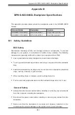
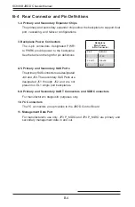
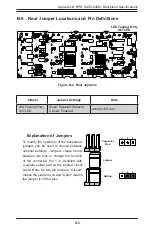
B-4 Rear Connector and Pin Definitions
1-2. Primary and Secondary Expander Chips
The primary and secondary expander chips allow the backplane to support dual
port, cascading, and failover configurations.
Backplane
Main Power
4-Pin Connector
Pin# Definition
1
+12V
2 and 3
Ground
4
+5V
3. Backplane Power Connectors
The 4-pin connectors, designated PWR1
to PWR6 provide power to the backplane.
See the table on the right for pin definitions.
4-5. Primary and Secondary SAS Ports
The primary SAS connectors are designated
J49 and J50. The secondary SAS Ports are
designated J51 through J52 and are not
present on EL1 single port backplanes.
6-9. Primary and Secondary UART Connectors and SDB Connectors
For manufacturer's diagnostic purposes only.
10. I
2
C Connectors
The I
2
C connectors accept cables to the JBOD Control Board.
11. Management Data Port
For manufacturer's use only. JP3 P_MDIO and JP4 P_MDIO are primary and
secondary management data in and out.

