27
Chapter 3: Maintenance and Component Installation
SAS Cables
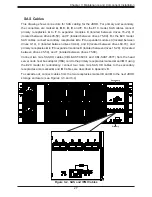
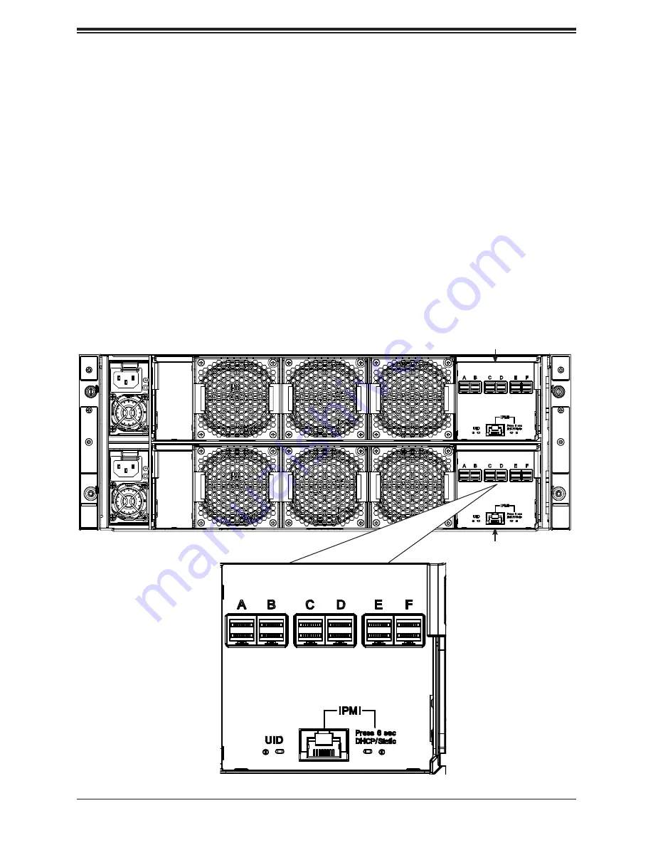
This drawing shows connectors for SAS cabling for the JBOD. For primary and secondary,
the connectors are marked
A
,
B
,
C
,
D
,
E
, and
F
. For the E1C model, SAS cables connect
primary receptacles
A
to
F
to expander modules B (located between drives 15-29), D
(located between drives 45-59), and F (located between drives 75-89). For the E2C model,
SAS cables connect secondary receptacles
A
to
F
to expander modules A (located between
drives 0-14), C (located between drives 30-44), and E (located between drives 60-74), and
primary receptacles
A
to
F
to expander modules B (located between drives 15-29), D (located
between drives 45-59), and F (located between drives 75-89).
Connect two mini-SAS HD cables (CBL-SAST-0690-1 and CBL-SAST-0677) from the head
server node host bus adapter (HBA) card to the primary receptacles marked
A
and
B
. If using
the E2C model for redundancy, connect two more mini-SAS HD cables to the secondary
receptacles also marked
A
and
B
. Cables are described in Appendix B.
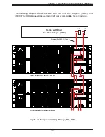
To cascade out, connect cables from the two receptacles marked
C
and
D
to the next JBOD
storage enclosure (see Figures 3-3 and 3-4).
Figure 3-2. SAS and IPMI Cables
Primary
Secondary

