background image

USER’S MANUAL 

Revision 2.0

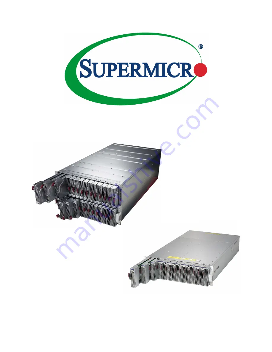
MicroBlade Enclosures

Summary of Contents for MicroBlade MBE-628E-416

Page 1: ...USER S MANUAL Revision 2 0 MicroBlade Enclosures...

Page 2: ...lass A device or in residential environment for Class B device This equipment generates uses and can radiate radio frequency energy and if not installed and used in accordance with the manufacturer s...

Page 3: ...ssary drivers utilities and the user s manual for your server Supermicro product manuals www supermicro com support manuals Product safety info www supermicro com about policies safety_information cfm...

Page 4: ...tem 14 2 3 Preparing for Setup 14 Choosing a Setup Location 14 Rack Precautions 15 Rack Mounting Considerations 15 Ambient Operating Temperature 15 Airflow 15 Mechanical Loading 15 Circuit Overloading...

Page 5: ...dancy 32 Determining Master Slave Modules Status 32 5 2 Installation 32 5 3 Configuring the CMM 33 Configuring the CMM in Windows OS 34 5 4 CMM Functions 36 Remote KVM over IP 36 Remote Storage Virtua...

Page 6: ...Super Micro Computer B V Het Sterrenbeeld 28 5215 ML s Hertogenbosch The Netherlands Tel 31 0 73 6400390 Fax 31 0 73 6416525 Email sales supermicro nl General Information support supermicro nl Technic...

Page 7: ...tus fault status Operating Systems Microsoft Windows VM Ware and Linux operating systems are supported by the MicroBlade servers Different operating systems can run on different blades within the same...

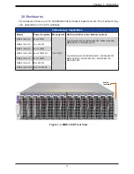
Page 8: ...pabilities Model Power Supplies Manage Options Switch Options MBE 628E 422 Four 2200W Up to two CMMs Two MBM GEM 004 MBM GEM 001 MBM XEM 001 MBM XEM 002 MBM XEM 002 MBM XEM 100 MBM 25G P20 MBE 628EB 4...

Page 9: ...Indicators Green All blades switch modules CMM power supplies and fans are operating normally Red Critical warning some components or modules are not operating normally LAN Port Network port for the...

Page 10: ...ules CMMs 4 Switches Note For the following blade servers all networking goes through the switch in the A1 slot upper left slot so the switch in the other slot will not work with the blade network MBI...

Page 11: ...GbE Switch Pass thru Module Options MBE 314E 422 Four 2200W One CMM Two MBM GEM 004 MBM XEM 002 MBM XEM 002 MBM XEM 100 MBM 25G P20 MBE 314E 222 Two 2200W MBE 314E 420 Four 2000W Two MBM GEM 004 MBM G...

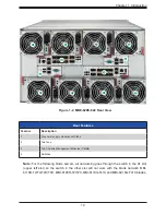
Page 12: ...12 Chapter 1 Introduction 2 1 1 1 1 3 3 Rear Features Feature Description 1 Four power supply modules with fans 2 Chassis Control Module CMM 3 Switches Figure 1 4 MBE 314E 420 Rear View...

Page 13: ...40Gbps QSFP uplinks 56x 10Gbps or 1Gbps downlinks one console port one USB port MBM XEM 002 Broadcom Low Latency Switch 56x 10Gbps Internal Ports 2x 40Gbps QSFP and 4x 10 Gbps SFP External Uplink Port...

Page 14: ...for Setup The box in which the system was shipped should include the rackmount hardware needed to install it into the rack Please read this section in its entirety before you begin the installation Ch...

Page 15: ...up Use a regulating uninterruptible power supply UPS to protect the server from power surges and voltage spikes and to keep your system operating in case of a power failure Allow power supply modules...

Page 16: ...nections other than the direct connections to the branch circuit i e the use of power strips etc Warning To prevent bodily injury when mounting or servicing this unit in a rack you must take special p...

Page 17: ...ed use the template to mark the position that the enclosure will occupy on the rack The chassis comes with two sets of rack rails one set for the right side of the chassis and one for the left 1 For e...

Page 18: ...ver to lock it into place Figure 2 4 Enclosure Installed Note The figure above is for illustrative purposes only Always install enclosures at the bottom of the rack first Stability hazard The rack sta...

Page 19: ...t match the specifications and or part numbers given 3 1 Removing Power Use the following procedure to ensure that power has been removed from the system This step is necessary when removing or instal...

Page 20: ...all Power Supply Modules details in Chapter 4 Fans CMM Switches or pass thru modules Blade servers In all cases slide the component into the enclosure then secure with the locking lever Note All modul...

Page 21: ...king lever on the blade and slowly push it into its bay 2 When the blade is seated in the bay push the locking lever into its locked position making sure the notches in both handles catch the lip of t...

Page 22: ...r MicroBlade system and check the packing list for damaged or missing components 2 Mount the MicroBlade enclosure in your server rack Chapter 2 3 Install the power supply modules into the rear of the...

Page 23: ...Figure 4 1 Example Power and Fan Module PWS 1K67P 1R 4 1 Module Description An LED status indicator is located near the locking lever Status Indictor Color Description Red Power module failure Amber...

Page 24: ...vertently put a power supply upside down it can be very difficult to remove 2 Push unit all the way in until it is firmly seated 3 Push the locking handle into the closed position until it clicks into...

Page 25: ...rposes of denoting the amount of redundancy a server system has N main power supplies to support the whole system N n denotes n the number of redundant power supplies For example N 1 describes a syste...

Page 26: ...s include a system fan If some bays in an enclosure are not filled with power supply modules the can house similar sized fan modules If a power supply fails its fan will continue to operate to provide...

Page 27: ...ut 14 2 12A 120 140Vac input 13 7 11 7A 200 240Vac input 9 4 7A Rated Frequency 50 60HZ Maximum Power 100 120Vac input 1200W 120 140Vac input 1400W 200 240Vac input 1600W Efficiency Certification 80Pl...

Page 28: ...nly Efficiency Certification 80Plus Platinum 96 230Vac 50 Loading 12V Output 1000W 1600W 1980W 2000W 83 3A 150A 165A 166 7A 12Vsb DC Output 4 2A Operating Conditions Operating Temp 0 to 50 C up to 500...

Page 29: ...200 240Vac Input 183 3A UL cUL Only Rated Frequency 50 60HZ Maximum Power UL cUL North America 200 220V 2090W 220 240V 2200W Rest of the world 100 127V 1200W 200 220V 1800W 220 230V 1980W 230 240V 209...

Page 30: ...are the MBM CMM FIO MBM CMM FIO V or MBM CMM 001 5 1 Features Figure 5 1 MBM CMM FIO Module Interface MBM CMM FIO Feature Description Management Capabilities Can manage up to 28 blade units network m...

Page 31: ...MM 001 Module Interface MBM CMM 001 Feature Description Management Capabilities Can manage up to 28 blade units network modules and eight power supplies Ports Two Ethernet ports one serial port and tw...

Page 32: ...d a master slave status This is done automatically with the default primary CMM specified for per each enclosure while there will be no redundant in certain enclosures If the master CMM is powered dow...

Page 33: ...into the default Fail Over mode The DHCP mode will appear on the CLI mode screen If the system failover and CLI is not active it will proceed to the default IP access If the CMM cannot enter the defa...

Page 34: ...w Properties 3 On the General tab page choose Internet Protocol TCP IP and click Properties Figure 5 3 Configuring CMM Choose Protocol 4 Manually configure the IP address of the computer system to be...

Page 35: ...essed through the web browser by entering the default IP address 192 168 100 100 of the CMM into the browser s address bar Now the IP address subnet mask and default gateway of the CMM can be changed...

Page 36: ...o issue similar or identical commands to many MIcroBlade enclosures CMM to manage all of them in a similar way Remote KVM over IP Remote KVM over IP is independent from local KVM although local KVM ca...

Page 37: ...hether there is enough power for this new blade module by comparing the Max Power Consumption value of the new blade module with the calculated Remaining Power value of the system If there is enough p...

Page 38: ...nt activities The Web based Management Utility is a web based interface that consolidates and simplifies system management for Supermicro MicroBlade systems The Web based Management Utility aggregates...

Page 39: ...label on the motherboard For more information please refer to our website at https www supermicro com en support BMC_Unique_Password and https www supermicro com support BMC_Unique_Password_Guide pdf...

Page 40: ...assistance Only certified technicians should attempt to install or configure components Read this appendix in its entirety before installing or configuring components in the Supermicro chassis These...

Page 41: ...idere los riesgos de la corriente el ctrica y familiar cese con los procedimientos est ndar de prevenci n de accidentes Al final de cada advertencia encontrar el n mero que le ayudar a encontrar el te...

Page 42: ...ient u zich bewust te zijn van de bij een elektrische installatie betrokken risico s en dient u op de hoogte te zijn van de standaard procedures om ongelukken te voorkomen Gebruik de nummers aan het e...

Page 43: ...n Attention Avant de brancher le syst me sur la source d alimentation consulter les directives d installation Circuit Breaker Waarschuwing Raadpleeg de installatie instructies voordat u het systeem o...

Page 44: ...el edificio Aseg rese de que el dispositivo de protecci n no sea superior a 250 V 20 A Attention Pour ce qui est de la protection contre les courts circuits surtension ce produit d pend de l installat...

Page 45: ...a y del cable el ctrico quitado de los m dulos de fuente de alimentaci n antes de tener acceso el interior del chasis para instalar o para quitar componentes de sistema Attention Le syst me doit tre...

Page 46: ...nt u alle spanningsbronnen en alle stroomkabels aangesloten op de voeding en van de behuizing te verwijderen Equipment Installation Warning Only trained and qualified personnel should be allowed to in...

Page 47: ...lar reemplazar o utilizar este equipo Attention Il est vivement recommand de confier l installation le remplacement et la maintenance de ces quipements des personnels qualifi s et exp riment s Warning...

Page 48: ...a de estas reas mediante la utilizaci n de una herramienta especial cerradura con llave u otro medio de seguridad Attention Cet appareil doit tre install e dans des zones d acc s r serv s L acc s une...

Page 49: ...e ou quivalent recommand e par le fabricant Jeter les piles usag es conform ment aux instructions du fabricant Advertencia Existe peligro de explosi n si la bater a se reemplaza de manera incorrecta R...

Page 50: ...evolen wordt Gebruikte batterijen dienen overeenkomstig fabrieksvoorschriften afgevoerd te worden Redundant Power Supplies Warning This unit might have more than one power supply connection All connec...

Page 51: ...te maken Advertencia Puede que esta unidad tenga m s de una conexi n para fuentes de alimentaci n Para cortar por completo el suministro de energ a deben desconectarse todas las conexiones Attention C...

Page 52: ...encia Cuando el sistema est en funcionamiento el voltaje del plano trasero es peligroso Tenga cuidado cuando lo revise Attention Lorsque le syst me est en fonctionnement des tensions lectriques circul...

Page 53: ...con las normas de electricidad locales y nacionales Backplane Waarschuwing Een gevaarlijke spanning of energie is aanwezig op de backplane wanneer het systeem in gebruik is Voorzichtigheid is geboden...

Page 54: ...lektriciteitsvoorschriften Warnung Die Entsorgung dieses Produkts sollte gem allen Bestimmungen und Gesetzen des Landes erfolgen Warning Ultimate disposal of this product should be handled according t...

Page 55: ...age de ce produit sont g n ralement soumis des lois et ou directives de respect de l environnement Renseignez vous aupr s de l organisme comp tent Hot Swap Fan Warning Warning Hazardous moving parts K...

Page 56: ...nilladores y todos los objetos lejos de las aberturas del ventilador Attention Pieces mobiles dangereuses Se tenir a l ecart des lames du ventilateur Il est possible que les ventilateurs soient toujou...

Page 57: ...r CAS zertifizierten Kabeln mit UL CSA gekennzeichnet an Ger ten oder Produkten die nicht mit Supermicro gekennzeichnet sind AC AC UL CSA UL CSA Supermicro Supermicro UL CSA UL CSA Supermicro UL CSA U...

Page 58: ...code pour tous les autres appareils lectriques sauf les produits d sign s par Supermicro seulement AC AC UL CSA UL CSA Supermicro UL CSA UL CSA Supermicro Advertencia Cuando instale el producto utilic...

Page 59: ...itmethode deze moet altijd voldoen aan de lokale voorschriften en veiligheidsnormen inclusief de juiste kabeldikte en stekker Het gebruik van niet geschikte Kabels en of Adapters kan een storing of br...

Page 60: ...perature 0 to 50 C up to 5000m Non operating Temperature 40 to 75 C up to 15200m Operating Relative Humidity 8 to 80 non condensing Non operating Relative Humidity 5 to 95 non condensing Regulatory Co...

Page 61: ...nia Best Management Practices Regulations for Perchlorate Materials This Perchlorate warning applies only to products containing CR Manganese Dioxide Lithium coin cells Perchlorate Material special ha...

Reviews: